Boiler Overview:
The circulating fluidized bed boiler is known for its exceptional fuel adaptability, enabling efficient utilization of low-quality fuels during combustion. Moreover, its low combustion temperature offers advantages such as reduced nitrogen oxide emissions. Consequently, the domestic circulating fluidized bed boiler has witnessed rapid development. However, the unique characteristics of the fuel and combustion process have led to significant wear and tear on the boiler heating surfaces, emerging as a primary cause of boiler leakage. Over the years, boiler design and production units have undertaken extensive research to address this issue and have proposed various anti-wear measures.
Wang Jia [1] conducted a numerical simulation investigating the impact of anti-wear beams on gas-solid flow characteristics of the water-cooled wall surface under different operating conditions. Similarly, Du Baozhong [2], Jianliangjun [3], Wang Lixin [4], and Lu Gang [5] have analyzed the wear mechanisms at different locations within circulating fluidized bed boilers. Xie Dejuan [6] conducted numerical simulations on gas-solid two-phase flow in the furnace chamber, focusing on the wear parameters of water-cooled wall tubes. However, these analyses lack comprehensive consideration of boundary conditions and neglect the disadvantages that excessive anti-wear measures may bring, resulting in suboptimal anti-wear solutions.

Various forms of anti-wear measures are commonly employed in circulating fluidized bed boilers, including the application of refractory materials on the boiler heating surface, metal spraying, metal dissolving, and the addition of anti-wear beams, partitions, fins, tiles, and grill anti-wear structures, among others. Passive anti-wear measures, such as laying refractory materials, have shown excellent anti-wear effects but significantly impact heat transfer, combustion, and power generation in the unit due to large-area coverage.
Active anti-wear methods involve adjusting the fluidization wind speed and optimizing the uniformity of the wind distribution plate. The utilization of metal grilles, anti-friction beams, or partitions has proven effective in reducing wall-flow fuel concentration, velocity, and direction, thereby improving the distribution of heat transfer. However, improper installation or dislodgment of these devices may lead to rapid wear leakage.
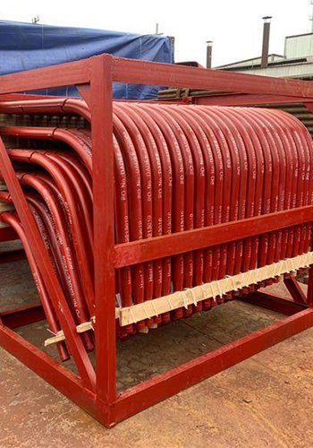
For serpentine pipe rows in the tail flue, the use of anti-friction Vado has shown favorable results in mitigating wear. Metal cladding serves as an efficient means to enhance the wear resistance of boiler heating surfaces with minimal impact on boiler heat transfer, but it is suitable only for localized anti-wear applications due to the need for replacement of boiler heating surfaces, which can be costly. Metal spraying is widely utilized to improve the wear resistance of boiler heating surfaces due to its low cost and limited impact on heat transfer.
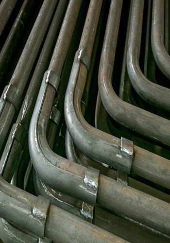
Anti-friction fins and anti-friction spacer beams serve similar purposes, being longitudinally welded to the tube surface as a whole.
In conclusion, addressing wear on boiler heating surfaces in circulating fluidized bed boilers requires a comprehensive and balanced approach that carefully considers the trade-offs between anti-wear measures and their impact on boiler performance. Through further research and optimization, more effective and efficient anti-wear solutions can be developed to ensure the long-term reliability and stability of circulating fluidized bed boilers.
Furnace Boiler Heating Surface Wear Mechanism:
Wear is a dynamic process that involves the consumption of kinetic energy by particles, leading to impacts on metal surfaces and causing material loss. Current research on wear analysis has identified key factors influencing the wear rate, including the impact rate, angle, and speed of particles. The wear rate is determined by the impact rate, particle concentration, impact speed, and is mathematically described by formula (1). Mechanical analysis reveals that wear occurs due to contact and pressure between objects, with the wear rate being proportional to the object’s hardness, pressure, tangential force, and contact area.

The wear of boiler heating surfaces is influenced by various parameters, including time, hardness of the boiler heating surface material, pressure, tangential force, and contact area. Additionally, the wear rate of the boiler heating surface tubes is directly proportional to the square of the particle diameter. Notably, fly ash particles smaller than 40 μm do not cause abrasion on the tube surface as they bypass the tube along with the flue gas [7].
The wear rate (T) of the metal surface on the pipe wall is expressed by formula (1):
T = C · η · μ · w3 · τ (1)
Where:
T – Abrasion of the metal surface of the pipe wall, measured in g/m2;
τ – Time of wear, measured in hours;
η – Fly ash impact rate;
μ – Mass concentration of fly ash particles, measured in g/m3;
w – Flow rate of fly ash particles, measured in m/s;
C – Wear characteristics of fly ash particles.
Wear Analysis of Boiler Heating Surface in Circulating Fluidized Bed Furnace Chamber:
The circulating fluidized bed (CFB) boiler primarily utilizes low-calorific value fuel, which is characterized by high hardness, large particle size, low volatile matter, and high ash content. In the furnace chamber, the fuel undergoes combustion in a fluidized state and is subsequently separated and recirculated. The fuel concentration, velocity, and direction in different regions of the furnace chamber are determined by the boiler’s fluidization characteristics, the arrangement of the wind and smoke system, and the overall boiler structure. The varying furnace structures, fuel properties, design parameters, and operating conditions result in different degrees of wear on the boiler heating surfaces of the boiler hearth, varying across different regions. Nonetheless, the fundamental principle governing furnace wear remains the same, allowing us to optimize anti-wear measures for each specific region, utilizing different operating conditions and fuel properties as benchmarks.
This analysis aims to examine the wear patterns on various parts of the boiler heating surface within the furnace chamber of a circulating fluidized bed boiler, taking into account the unique characteristics of the fuel and flue gas movement. By comparing the wear in similar areas, we will develop rational anti-wear measures.

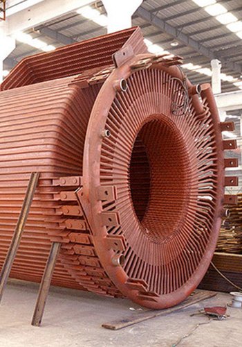
To illustrate the wear analysis, we will consider the example of a 2×300MW circulating fluidized bed boiler operating in a power plant. This particular boiler is designed and manufactured by Dongfang Boiler (Group) Co., Ltd., featuring a circulating fluidized bed system, subcritical parameters, natural circulation steam bag furnace, and a cyclone gas-solid separator. The boiler’s core components include a membrane-type water-cooled wall furnace, three cooled cyclone separators, and a vapor-cooled package wall enclosing the tail shaft (HRA). Additionally, the furnace is equipped with six medium-temperature superheater tube screens, six high-temperature superheater tube screens, six high-temperature reheater tube screens, and a water-cooled partition wall in the front. Furthermore, the rear wall features two water-cooled evaporator screens.
By analyzing the wear patterns in the aforementioned components and regions, we can develop effective anti-wear measures tailored to the specific operational conditions and fuel properties of this circulating fluidized bed boiler. The goal is to enhance the longevity and performance of the boiler heating surfaces, ensuring efficient and reliable boiler operation.
Water-cooled Air Chamber in the Furnace:
The water-cooled air chamber comprises water-cooled wall pipes, fins, and air cloth plates, with the latter consisting of water-cooled wall pipes, fins, and air caps. The air chamber adopts a two-side air inlet configuration, where the inlet is formed by the side wall with thinning indentation. The bottom of the furnace wind cloth plate is lined with a 75mm thick wear-resistant plastic material, surrounded by refractory casting material, forming a 150mm high wear-resistant step. The top of the air chamber is made of wear-resistant plastic, while the rest of the air chamber is constructed using a 53.5mm refractory castable material.
Functionally, the water-cooled air chamber acts as a container, temporarily storing the fluidized air from the air distribution board, converting dynamic pressure to static pressure, reducing the wind speed, and serving as a buffer. The fluidized air is drawn from the hot primary air after passing through the air preheater. The air pre-preparator, comprising four parts, is positioned back to back, with the primary wind located in the middle of the wind side. The second wind, carrying reduced concentrations of fly ash and smaller particles, is blown from the heat storage element. The water-cooled air chamber mainly protects wear-prone components, such as the water-cooled wall tubes, fins, and cap core tubes. The primary wind, carrying fly ash from the primary air duct, enters the chamber through the inlet, accelerating and supplementing the primary wind within the air chamber. The primary wind inside the air chamber moves gradually towards the air distribution board, with higher speed in the middle and slower speed around the periphery.

Analyzing the wear of components inside the air chamber, the concentration of fly ash remains relatively consistent. One of the most significant areas of higher wind speed is at the entrance of the wind chamber, where the change in wind direction due to the indentation results in an oblique cutting force, causing the highest wear. In contrast, the bottom of the wind cloth plate and other parts of the wind chamber experience lower wind speeds and, consequently, less wear. Notably, the inlet dilution tube experiences a larger and more forceful impact, resulting in significant wear due to tangential forces. Comparatively, the wear amount in the inlet dilution tube can be likened to that of the internal support rod of the hot primary duct, while the turning area can be compared to similar parts in the roof of the package wall and the partition wall.
To ensure long-term stable operation, appropriate wear-resistant measures are implemented. The inlet dilution tube area may be lined with castables or anti-wear tiles, and the turning area may be subjected to metal spraying or the laying of wear-resistant materials. However, full coverage of wear-resistant materials may not be necessary in all areas. Careful optimization of wear-resistant measures will help enhance the durability and performance of the water-cooled air chamber in the circulating fluidized bed boiler.
Wind Cloth Plate in the Furnace:
The wind cloth plate is composed of the wind cap, water-cooled wall pipes, and fins, serving as a crucial element for securing the wind cap and transporting fuel within the furnace. Within the wind cloth plate area, the diameter of fuel particles reaches approximately 1mm. These fuel particles undergo irregular high-speed movements due to the strong wind speed within the wind cap holes. Simultaneously, they are subject to ash return and direct scouring from the downward slant of the coal feeder’s fuel supply. Furthermore, a considerable number of larger fuel particles scour along the water-cooled wall, eventually settling after fluidization. The presence of large particles, varying hardness, irregular concentration, multiple directions, and high-speed movements contribute to an accelerated wear rate in the wind cloth plate area.
To address this wear issue effectively, the wind cloth plate is reinforced with wear-resistant materials, ensuring secure fixation. Additionally, buffer tabs are strategically placed around the wind cloth plate to mitigate wear impact. The wind cap itself is constructed with wear-resistant materials and employs a thickened structure to enhance durability against the wear caused by high-speed fuel particles.
By implementing these wear-resistant measures and enhancing the structural integrity of the wind cloth plate and wind cap, the circulating fluidized bed boiler can achieve improved longevity and performance, with minimized wear-related issues in this critical region.
Dense Phase Area in the Boiler Hearth:
The dense phase area in the boiler hearth is characterized by an upper rectangular section and a lower indentation with a trapezoidal shape. Within this section, various components are arranged, including the coal feed port, second air outlet, return port, bed temperature measurement point, and slag discharge port. The cone section of this area is commonly referred to as the dense-phase zone. In the dense phase area, the primary air flow carries fuel and limestone, resulting in the rise of fine particles with large particles descending to a certain height. The effective bed material continues to rise, leading to the formation of a thin-phase area in the upper part, dominated by fine particle fluidization, and a dense-phase area in the lower part, dominated by fluidization of large particles.
Due to the influence of wind from the secondary air inlet, coal feed inlet, feeder, and slag cooler, the bed material undergoes high-speed and irregular movements, leading to the occurrence of vortex phenomena in some regions. The dense-phase area experiences internal circulation of fuel, while the four walls of the furnace chamber act as boundaries to prevent the diffusion of bed material and change its direction. Additionally, the corner parts of the hearth collect the bed material from two directions, leading to increased concentration and speed. The upper part of the dense-phase area causes large particles to land on the front and rear walls’ slopes, altering their continued movement direction and exerting pressure and tangential force on the surrounding heated surfaces. The construction of hearth corner parts, considered field splicing welding areas, introduces gap inconsistency, thereby increasing the cutting force in localized regions. The bed material in the dense phase zone is characterized by large and hard particle diameters.
Considering these factors, the dense phase area experiences significant overall wear and tear, necessitating the implementation of wear-resistant plastic and firm fixation. The wear amount primarily refers to the wear on the cloth wind plate, wind cap, temperature casing, and other components within this region.
To effectively address the wear challenges in the dense phase area, strategic deployment of wear-resistant measures, such as the application of wear-resistant plastic and ensuring firm fixation, will enhance the durability and performance of the circulating fluidized bed boiler in this critical section.
Rare-phase Area in the Furnace:
The rare-phase area in the furnace chamber is situated at the upper portion of the front wall, where it accommodates six pieces each of medium-temperature superheater tube screens, high-temperature superheater tube screens, high-temperature reheater tube screens, and a water-cooled partition wall. The rear wall features two water-cooled evaporation screens and connects to the furnace’s three outlets and separator. Zhang Ximei et al. [8] have confirmed that the offset outlet arrangement significantly influences the particle flow structure in the outlet region of the bed. In the dilute-phase region, the material experiences rapid fluidization, whereas the relatively dense-phase region exhibits lower material concentration and smaller particle size, with the flue gas carrying the movement of fly ash. Overall, the flue gas moves upward and backward in the upper rare-phase region of the furnace chamber. As the cross-sectional area narrows at the hearth exit, the flue gas flow rate increases, and a portion of the flue gas moving upwards reaches the top and moves downward and backward toward the hearth exit.

In the front wall area of the furnace, fuel is influenced by the direction of the flue gas moving toward the rear wall. The contact between the material and the tube wall is reduced, but some fuel is still constrained by the boundary and moves along the left and right side walls from front to back. Under the influence of the wind from the three outlets on the rear wall, the material moves in different directions. Near the water-cooled walls of the left and right side walls, the fuel concentration and velocity are distributed from front to back, from dilute to dense, due to the superposition of material moving from front to back and the material near the original back wall. In the height direction, the distribution changes from dense to dilute from bottom to top, with the movement direction being from bottom to top and backward, leading to an increase in the proportion of backward cutting force. Based on the analysis, the region near the furnace exit and close to the back wall experiences the most severe wear. To mitigate wear in this region, it is recommended to consider measures such as reducing speed, pressure, and direction variability, such as using anti-wear fins or applying effective metal fusion coatings. In cases of severe wear, laying wear-resistant materials may be necessary. Other areas can employ more economical methods, such as metal spraying.
The water-cooled evaporation screen and side walls face similar wear challenges, and similar anti-wear methods can be adopted. However, it is worth noting that the design of the right water-cooled evaporation screen in the boiler plant uses double-sided casting material, while the right side of the water-cooled evaporation screen utilizes single-sided casting material for anti-wear. This approach may lead to excessive anti-wear measures.
In the furnace front wall, the material moves backward, and its contact concentration and pressure with the tube wall are low, resulting in small particle diameters and relatively low abrasion rates. To prolong the service life, it is suggested to utilize metal spraying for anti-abrasion in the region close to the dense-phase area.
In the back wall of the furnace, the material experiences movement in the direction of the three outlets under the influence of flue gas. The region below the exit elevation moves upward and backward, while the region above the exit moves downward and closer to the direction of the three outlets. The concentration of the material changes from thick to thin and then to thick from bottom to top, with the particles changing from large to small. The movement direction is oblique, generating oblique shear forces. In this region, anti-wear methods such as metal spraying and grill anti-friction can be employed, considering the hardness of the fuel and the size of the particulate matter.
The front wall arrangement of pipe screens through the wall introduces changes in material direction, increasing wear and tear. To address this, the design incorporates laying casting material to form a square boundary for all parts through the wall, ensuring sealing and blocking gaps. For the horizontal arrangement of pipe screens, the tube bundle experiences upward and backward movement of flue gas fly ash, leading to the formation of diagonal shear forces and local vortexes. In this case, metal spraying and the laying of castables are suitable methods. As for the vertical tube bundle, it can be referenced to the side wall water-cooled wall and may not require specific anti-wear measures or metal spraying.
The furnace ceiling experiences flue gas fly ash movement from front to back, first upward and then downward, with low fly ash concentration and small cutting force under the negative pressure of the furnace outlet. As a result, wear is minimal, and anti-wear measures or metal spraying may not be necessary. For the ceiling hanging screens through the wall, sealing measures are sufficient without the need for additional anti-friction methods.
Other Special Areas in the Furnace:
Certain areas in the furnace require special attention to prevent wear and ensure effective operation. For instance, temperature and pressure casings serve as open areas that require sealing while providing anti-wear functionality. To achieve this, the tube positions are covered with casting material to form a sealing box. The horizontal direction boundary of the casting material is crucial, as particles impact the downward movement, causing irregular movements and impacting the heated surface tubes. The presence of ash accumulation in this region acts as a buffer, absorbing part of the kinetic energy and reducing abrasion. It is essential to strictly avoid creating diagonally downward boundaries, as this may lead to severe “eight” shaped wear in the root of the heated surface tubes. Additionally, vertical boundaries must be neat to avoid local vortex formations that can cause wear on the boiler heating surface.
During field installation, dimensional errors can occur, resulting in uneven surfaces, especially in butt welds, under the influence of wall flow and oblique cutting forces. These factors lead to thinning of the tubes, particularly in areas close to the dense-phase zone.
Moreover, all entrapment parts in the furnace chamber experience material lifted by the flue gas lifting force, with most of the material colliding with the heated surface and rapidly descending. In areas with high speed, concentration, and installation errors, wear is most pronounced. It is crucial to focus on these areas and implement effective anti-wear measures, such as reducing the speed of particulate matter or enhancing the abrasion resistance of the heated surface. Measures like adding multi-layer partitions or laying wear-resistant materials can prove beneficial in addressing wear challenges in these regions.
By proactively addressing the wear concerns in these special areas and adopting appropriate anti-wear measures, the circulating fluidized bed boiler can achieve enhanced durability and optimal performance throughout its operational lifespan.
Summary:
The movement of fuel and particulate matter in the furnace chamber of a circulating fluidized bed boiler is complex, and the specific wear-related factors cannot be precisely calculated due to changes in operating conditions and fuel characteristics. This study combines the understanding of the motion inside the furnace chamber with the wear mechanism to analyze wear in each region. By comparing similar wear regions, the study proposes reasonable anti-wear measures to avoid both excessive and insufficient anti-wear.
Taking a 300MW/h power plant boiler as an example, the analysis and comparison lead to the following conclusions:
- Water-cooled air chamber wear can be compared to the wear on the primary duct support bar, and having the water-cooled air chamber fully covered with wear-resistant materials indicates excessive anti-wear.
- Water-cooled evaporation screen wear can be compared to the wear on the left and right side walls, and using large areas of casting material for anti-wear can lead to excessive anti-wear.
- The corners of the furnace chamber were not designed to account for the unevenness of field installation gaps, resulting in a lack of anti-abrasion measures in those areas.
- For the ceiling hanging screen through the wall parts, the fuel granularity is small, and the forces are small, necessitating only sealing measures without additional anti-wear measures.
By implementing appropriate anti-wear measures based on these findings, the circulating fluidized bed boiler can achieve optimal performance and durability, while avoiding unnecessary wear-related issues.
[Source] Xu Chengxing, Shanxi Guofeng Coal Power Co., Ltd., Shanxi, 032202, Modern Chemical Research:2023.14 52-54
[1] Wang Jia. Research on water-cooled wall wear and anti-wear of circulating fluidized bed boiler [D]. Shandong University of Technology,2020.
[2] Du Baozhong. Research on wear and prevention technology of heating surface of circulating fluidized bed boiler[D]. North China Electric Power University,2014.
[3] Jie Liangjun. Study on fluidization uniformity and wear in the dense phase region of 300MWCFB boiler hearth[D]. Shanghai Jiao Tong University,2011.
[4] Wang LX. Research on anti-wear technology of water-cooled wall in circulating fluidized bed boiler[D]. North China Electric Power University (Hebei), 2007.
[5] Lu Gang. Study on the wear characteristics of water-cooled wall in circulating fluidized bed boiler [D]. North China Electric Power University (Hebei), 2005.
[6] Xie Dejuan. 1025t/h circulating fluidized bed boiler furnace flow field simulation and wear analysis[D]. North China Electric Power University,2012.
[7] Hunan Electrical Engineering Society. Failure analysis and protection of boiler heating surface in thermal power plant boilers[M]. China Electrical Press, 2004.
[8] Zhang Ximei. Experimental study on the influence of structural arrangement on gas-solid flow characteristics in circulating fluidized bed[D]. Zhejiang University, 2010