Article Introduction: Revolutionizing Waste Incineration with Circulating Fluidized Bed Boilers
In response to the escalating urban waste challenge, China has embraced the prowess of Circulating Fluidized Bed (CFB) boilers for incineration. Originating in the 1980s, this technology, pioneered by institutions like Zhejiang University, has evolved into a cornerstone of waste management.
In 2021, China achieved a 99.7% harmless treatment rate for urban waste, with CFB technology dominating waste incineration. The journey from a modest 150 t/d capacity to a significant 1,000 t/d showcases China’s commitment to innovation.
This article explores a specific 1,000 t/d CFB waste incineration boiler, unveiling structural nuances and optimization’s transformative impact. With upgraded air distribution, return material systems, and more, the boiler now surpasses design efficiency, highlighting the economic and social benefits of China’s waste-to-energy evolution.
With the expansion of cities and the growth of urban populations, the annual production of municipal solid waste continues to increase. In 2021, the clearance volume of urban solid waste in China reached 249 million tons, maintaining an overall upward trend. The harmless treatment rate has steadily increased, as shown in Figure 1. By the end of 2021, the nationwide harmless treatment rate of urban solid waste had reached 99.7%, with municipal solid waste incineration accounting for 72.54% of the harmless treatment volume in China [1].
The first municipal solid waste incineration power plant in China was established in 1988 [2]. After more than 30 years of development, incorporating the introduction of advanced incineration equipment and technology from abroad, digestion, absorption, and optimization, it has gone through stages of industrialized research and development and equipment localization. The scale of waste treatment has also expanded from 150 t/d to over 1,000 t/d. Incineration has become the primary method of municipal solid waste disposal.
According to the “China Urban and Rural Construction Statistical Yearbook” (2021) [1], as of 2021, there were 583 incineration plants nationwide, with a total incineration capacity of 719,500 tons/day and an annual incineration capacity of 180,196,600 tons. These plants are mainly distributed in provinces and cities such as Guangdong, Shandong, Zhejiang, Jiangsu, Hebei, and Sichuan, as illustrated in Figure 2. The mainstream technologies adopted by these municipal solid waste incineration plants are the grate incineration technology and circulating fluidized bed incineration technology.

Development and Advancements in Circulating Fluidized Bed Municipal Solid Waste Incineration Technology in China
The inception of circulating fluidized bed garbage incineration technology in China dates back to the 1980s [3], with universities and research institutes, primarily led by Zhejiang University and the Institute of Process Engineering of the Chinese Academy of Sciences, taking the lead in its development. The circulating fluidized bed municipal solid waste incineration and power generation technology gained prominence due to its high heat storage capacity and low requirements for fuel moisture and ash content, making it suitable for China’s complex composition of municipal solid waste. Moreover, the low investment cost and high localization rate of circulating fluidized bed technology contributed to its vigorous development in China. As of now, China boasts the world’s highest installed capacity of circulating fluidized bed units, making it one of the mainstream technologies for waste incineration in the country.
With continuous improvements and enhancements, the steam parameters of circulating fluidized bed municipal solid waste incineration boilers have evolved from medium temperature and medium pressure (3.82 MPa, 450 ℃) to high temperature and high pressure (5.2 MPa, 485 ℃, and 7.9 MPa, 520 ℃) [4]. Currently, the domestically developed circulating fluidized bed incineration boiler with the highest steam parameters in stable commercial operation in China is the 7.9 MPa, 520 ℃ municipal solid waste circulating fluidized bed incineration boiler introduced by Hangzhou Jinjiang Group from Finland.
Through the localization research and development of high-parameter municipal solid waste circulating fluidized bed incineration technology, a certain power plant has applied domestic technology. It adopted a domestically developed 1,000 t/d municipal solid waste circulating fluidized bed incineration boiler, with key design parameters: rated evaporation capacity of 132 t/h, rated steam pressure of 7.9 MPa, rated steam temperature of 520 ℃, feedwater temperature of 132 ℃, and a design fuel heating value of 10,464.63 kJ/kg, categorizing it as a high-parameter circulating fluidized bed boiler [5]. The unit was completed, commissioned, and underwent trial operation in October 2019.
1. Original Structure of the Fluidized Bed Boiler
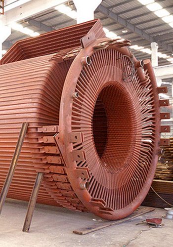
The boiler comprises a membrane-type water-cooled furnace chamber, two cyclone-type primary adiabatic separators, a wall-mounted water-cooled furnace settling and rising flue, a horizontal flue, four cyclone-type secondary adiabatic separators, and a rear vertical well flue.
Within the furnace chamber, a medium-temperature screen superheater is arranged. A high-temperature screen superheater is positioned in the rising flue of the wall-mounted water-cooled furnace, and an ash hopper is located at the corner where the settling flue and rising flue connect. The fly ash naturally settled in the wall-mounted water-cooled furnace is discharged outside the furnace through the bottom ash discharge port of the ash hopper.
The horizontal flue sequentially houses an evaporator and a low-temperature superheater. The horizontal flue, consisting of steam-cooled wall membrane, is equipped with four ash hoppers and ash discharge devices. The fly ash settled naturally in the horizontal flue is discharged outside the furnace through the bottom ash discharge port of the ash hopper. At the exit of the horizontal flue, there is a secondary cyclone separation device, arranged in two groups of left and right, with two cyclone separators in each group, totaling four cyclone separators.
Between the low-temperature superheater space, medium-temperature screen superheater, and high-temperature screen superheater, water spray coolers are installed to control the outlet temperature of the superheater.

Fig. 3: Arrangement of the Original Fluidized Bed Boiler
1- Furnace chamber
2- Medium temperature screen superheater
3- Cyclone separator
4- High temperature screen superheater
5- Low temperature superheater
6- Secondary separator
7- Coal economizer
2. Boiler Trial Run Situation
During the trial run, several issues were identified, including frequent blockage of the slag discharge port, severe ash leakage at the feed end of the cold slag machine drum, difficulty in clearing blockages, and frequent spontaneous ash flow. Additionally, there were challenges with ash settling and inadequate conveyance in the boiler body, medium-temperature screen outlet exceeding temperature limits, and difficulty in controlling the main steam temperature. Furthermore, the boiler’s output was significantly below the design value, with steam evaporation ranging only from 41% to 50%, making stable operation unattainable. The furnace combustion temperature also failed to meet environmental standards, as detailed in Table 1.
Table 1: Trial Run Values vs. Design Values
| No. | Name (Unit) | Design Value | Trial Run Value |
|---|---|---|---|
| 1 | Evaporation (t·h⁻¹) | 132 | 50~66 |
| 2 | Waste disposal capacity (t·d⁻¹) | 1000 | 510~675 |
| 3 | Steam pressure (MPa) | 7.9 | 7.5 |
| 4 | Steam temperature (°C) | 520 | 520 |
| 5 | Furnace outlet temperature (°C) | 885 | 760 |
| 6 | Boiler exhaust temperature (°C) | 165 | 124 |
| 7 | Boiler body resistance (Pa) | 4800 | 3000 |
3. Main Causes Analysis
(1) Unreasonable Air Distribution and Poor Slag Discharge
The boiler’s air distribution plates are arranged in a double W shape, hindering lateral fuel diffusion, leading to material accumulation and slag blockage. The mismatched quantity and position of waste feeding and slag discharge ports result in difficulties in discharging large, non-combustible waste, leading to potential furnace blockage. The layout of the return material box body rotation contributes to abnormal material return.
(2) Poor Fluidization and High Resistance
The furnace has a large heating surface, and the low-load screen superheater is prone to overheating. The exit temperature of the furnace is challenging to control. The use of a smoke-cooled air preheater with poor temperature adjustability makes bed temperature control difficult. The adoption of a secondary separation device leads to high resistance in the boiler body, making it challenging to quickly release boiler negative pressure fluctuations.
(3) Extended and Wear-Prone Furnace Heating Surface
The furnace’s medium and high-temperature screen superheaters are long, fixed on the lower side, prone to deformation and heating surface damage. The center positioning of the water-cooled wall expands both forwards and backward, with a small baffle plate connection between the primary separation outlet and the wall, causing material peeling or heating surface damage. The expansion joint on both sides of the horizontal flue bears weight on the heating surface tubes, leading to heating surface damage, and related issues have already been identified.
(4) Ineffective Soot Blowing System
During the trial run of the auxiliary system, it was found that using water soot blowing for the screen superheater caused deformation and damage to the heating surface.
The deeper issues reflected by these problems lie in the structural and thermal system design flaws of the original circulating fluidized bed boiler.
4. Optimization Design Solutions
In order to improve combustion conditions, enhance boiler combustion efficiency, and achieve continuous stable operation, optimization adjustments were made to the original boiler, including air distribution plates, return material box, secondary separation device, and heating surface adjustments.
4.1 Optimization of Air Distribution Plates and Feeding Ports
Air distribution plates are a critical component of fluidized bed boilers, playing a role in supporting bed materials and uniformly distributing air [6]. The original boiler was designed with a “W” shaped air distribution plate, which was not conducive to lateral fuel diffusion, leading to material accumulation and slag blockage. To reduce construction workload, the garbage feeding port on the front wall of the furnace was maintained, and the existing air ducts were mostly unchanged. The slag discharge port was correspondingly changed to three, and the wind caps were replaced, adopting a mushroom head shape. The slag discharge pipes used heat-resistant cast steel with a diameter of φ350. The double W-shaped air distribution plate was changed to a horizontal air distribution plate. The feeding port was raised, and the center distance to the air distribution plate was adjusted to m. The inlet fuel chute at the water-cooled wall of the furnace remained unchanged. Simultaneously, adjustments were made to the secondary air duct and downcomer based on the feeding port position and changes to the air distribution plate collection box (see Fig. 4).

Fig. 4: Comparison before and after optimization of air distribution board
1-Drop chute 2-Double W-shaped air distribution board 3-4 slag discharge ports 4-Horizontal air distribution board 5-3 slag discharge ports
After the optimization adjustments, during a three-month trial run period, the slag discharge was smooth, and no blockage occurred.
4.2 Optimization of Return Material Box
The return material system is a unique system of circulating fluidized bed boilers, mainly used to ensure efficient material separation, maintain the stability of circulating materials, and prevent flue gas from the furnace entering the separator through the return system. The return material system consists of a gas-solid separator, a standpipe, and a return valve [7]. The return material system of this boiler was adjusted from transverse diffusion to L-shaped longitudinal diffusion, and the internal aperture of the standpipe was adjusted. The original return air cap had small holes, causing significant fan head loss. The return air cap was replaced, and after the adjustment, the boiler’s return material flow was smooth, ensuring the safe operation of the boiler (see Fig. 5).

Fig. 5: Comparison of reclaim system before and after optimization
1-Rewinder 2-Transverse diffusion reclaim 3-L-shape longitudinal diffusion reclaim
4.3 Optimization of Secondary Separation Device
To reduce the boiler body resistance, the secondary separation device of the boiler was removed, and a connection flue with an ash hopper was introduced (see Fig. 6). After removing the secondary separation device, the boiler body resistance significantly decreased, and the boiler load steadily increased.

Fig. 6: Comparison before and after optimization of the secondary separator
1-secondary separator 2-coal economizer 3-flue gas steering chamber
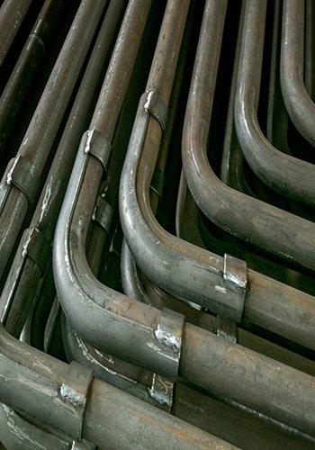
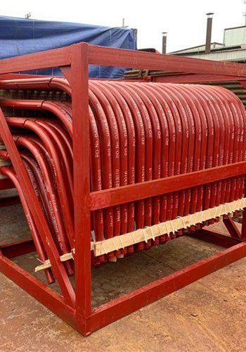
4.4 Optimization of Heating Surface
The medium-temperature overlay screen superheater in the furnace was removed, and its tubes were restructured for use in the high-temperature screen superheater. The original high-temperature overlay screen superheater tubes were restructured, changing the screen from L-shaped to U-shaped. The utilization of the overlay’s straight section was maintained, with the addition of a U-shaped tube at the bottom and a small header at the top. Professional treatment was applied to over 790 overlay joints, and external superheater connection pipes were adjusted accordingly. Based on the current garbage calorific value calculation, adjustments were made to the furnace heating surface. The original convective tube bundle was removed and replaced with a medium-temperature superheater. A convective tube bundle was added in front of the screen superheater to control the smoke temperature at the entrance of the screen superheater. Some high-temperature smoke coolers were changed to economizers, and high-temperature air heaters were changed to steam air preheaters. Simultaneously, top water soot blowing for the secondary flue was removed. After the adjustments, the boiler structure is as shown in Fig. 7.
5. Operational Effects after Design Optimization
Based on the current furnace cross-section and total heating surface area, combined with the initial parameters of the auxiliary equipment provided by the original boiler, calculated with a garbage calorific value of 9,208.87 kJ/kg, the boiler evaporation capacity reached 105 t/h, and the garbage processing capacity reached 1,000 t/d. After this optimization, the boiler’s operating parameters essentially achieved the desired design effects. The boiler load reached over 85% of the optimized design rated load, with steam temperature stabilized at 515-525°C and exhaust temperature ranging from 165 to 195°C. A comparison of various operational indicators is shown in Table 2.

Fig. 7: Schematic diagram of the optimized boiler structure
1 – Furnace 2 – High temperature screen superheater 3 – Cyclone separator 4 – Medium temperature screen superheater 5 – Low temperature superheater 6 – Coal economizer
Table 2: Comparison of Boiler Design and Operational Effects Before and After Optimization
| No. | Name (Unit) | Pre-optimization | After Optimization |
|---|---|---|---|
| 1 | Evaporation (t·h⁻¹) | 50~66 | 90 |
| 2 | Waste disposal capacity (t·d⁻¹) | 510~675 | 1000 |
| 3 | Steam pressure (MPa) | 7.5 | 7.9 |
| 4 | Steam temperature (°C) | 520 | 520 |
| 5 | Furnace outlet temperature (°C) | 760 | 857 |
| 6 | Boiler exhaust temperature (°C) | 124 | 170 |
| 7 | Boiler body resistance (Pa) | 3000 | 3100 |
According to the power plant’s operational data, the boiler’s evaporation capacity can reach 90 t/h, and it can operate continuously and steadily for more than three months. The evaporation capacity has increased by about 30 t/h, generating 280 kWh of electricity per ton of steam. With an annual operating hours of 8,000 hours and a cost of 0.65 yuan per kWh, the annual increase in electricity revenue is approximately 43.68 million yuan. Additionally, with an increase of 495 t/day in garbage processing capacity and a garbage processing fee of 75 yuan/t, the annual increase in garbage processing fees is 13.55 million yuan. The sum of these two amounts results in a total annual revenue increase of 57.23 million yuan per unit. With an additional daily processing capacity of 495 t of garbage, reaching an annual processing capacity of 180,000 t, it can significantly alleviate local waste disposal challenges, reduce the pressure of waste accumulation, enhance the power plant’s public image, and achieve positive social benefits.
6. Conclusion
Through the optimization and adjustment of the main body structure and heating surface of a 1,000 t/d circulating fluidized bed garbage incineration boiler, the implemented modifications have resulted in a garbage processing capacity of 1,000 t/d and a boiler evaporation capacity of 90 t/h. The boiler can meet the requirements of long-term, stable operation, demonstrating a significant improvement in performance. This serves as practical evidence of the effectiveness of the localization of (7.9 MPa/520°C) high-temperature and high-pressure circulating fluidized bed garbage incineration boilers. Furthermore, it has enhanced the economic and social benefits of the power plant.
References
[1] Ministry of Housing and Urban-Rural Development. Statistical Yearbook of Urban and Rural Construction in China [M]. Beijing:China Planning Press, 2022.
[2] Wu Jian, Jian Ruihuan, Liu Tao. Research on energy efficiency level of domestic waste incineration power plants in China [J]. Environmental sanitation engineering, 2018, 26( 3) : 39-42.
[3] Zhang Weiwei, Zhao Jiefei. Current situation and prospect of fluidized bed waste incineration boiler [J] Industrial Boiler, 2018( 2) : 1-7.
[4]GB/T 34552-2017 Fluidized bed incineration boiler for domestic waste [S].
[5] REN Chaofeng, FANG Chaojun, ZHU Shoubing, et al. Application of high parameter circulating fluidized bed waste incineration boiler technology [J]. Industrial Boiler, 2020( 4): 45-49.
[6] Guo Xuchao. The importance of the resistance of 300 MW circulating fluidized bed boiler cloth wind plate [J]. Science and technology wind, 2019( 21) : 1.
[7] Zhao Ru Nan, Jiang Sheng, Liu Xiao. Biomass circulating fluidized bed boiler return system clogging accident cause analysis, treatment and prevention [J]. China Power Education, 2019( 5) : 40-42.