Most industrial boilers employ the SCR catalytic reduction method for denitrification, alongside controlling the coal combustion process. Typically, SCR systems require a flue gas temperature ranging from 570 to 720 K and are usually positioned after the convection bundle but before the coal saver. The catalyst arrangement typically follows a one-to-one pattern, necessitating the reservation of approximately 7 to 9 meters of space, including the gas flow grille, two catalyst layers, and service area. This compression of space affects the height of the boiler economizer, air preheater, and service space, resulting in limited options for heating surface arrangement and elevated boiler exhaust temperatures. When considering locating the heating surface under the operating platform, one must also account for the foundation, steel frame, and flue duct arrangement, which can increase engineering volume and pose challenges in terms of technical and economic feasibility. Therefore, it is crucial to carefully consider the optimal arrangement of the heating surface, ensuring compliance with space requirements and smoke exhaust temperature regulations.
1 Boiler Room Structure
The structure of the boiler room is designed as follows: it is a purpose-built boiler room with a net utilization height of 21.2 meters. The boiler datum and operation platform are situated on the 7-meter plane. In the front and rear proximity directions, the center line distance between the boiler space columns is 21 meters. The large columns have a cross section of 1,000 mm × 500 mm, while the small columns have a cross section of 700 mm × 500 mm. A 6-meter-wide space surrounds the boiler room along the center line of the large columns. Additionally, there are 6-meter-wide areas designated for a locker room and an office. Furthermore, there is a 6-meter-long empty coal hopper space located in front of the boiler. In the front width direction of the boiler room, the center line distance of the large columns is 12 meters. The reserved space for the boiler furnace position measures 21 meters in length, 12 meters in width, and has a height of 21.2 meters.

2 H-type Boiler Economizer Structural Characteristics
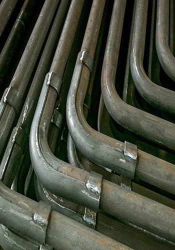
The H-type coal saver tube is classified as an extended heating surface, involving the addition of thin ribs welded onto the outer surface of the steel coal saver tubes to increase the external heat exchange area. There are two variations of the H-type coal saver: the double rib structure and the single rib structure. In the double rib structure, two straight sections of light tubes are longitudinally welded together with the ribs. On the other hand, the single rib structure consists of a single light tube welded with a rib. The commonly used tube diameters for the coal saver are Φ32 mm, Φ38 mm, Φ42 mm, and Φ51 mm. The ribs are typically made of pickled carbon steel with a thickness of 3 mm to ensure strong corrosion resistance. For the double rib structure, the height of the ribs is generally twice the longitudinal pitch of the tube, while the width is usually similar to the tube diameter. The heat transfer between the mass and the flue gas primarily occurs through inter-wall heat transfer.
The heat transfer process of the H-type economizer is characterized by its complexity, involving various heat transfer mechanisms. On the outer surface, the flue gas washes the economizer, while inside the tubes, heat transfer occurs through multiple processes. These processes include convection heat transfer between the flue gas and the outer wall of the tube, heat conduction from the outer wall to the inner wall of the tube, and convection heat transfer between the inner wall of the tube and the working mass. The overall heat transfer process comprises several steps: convection heat transfer between the flue gas and the ribs, heat conduction within the ribs themselves, heat conduction between the ribs and the outer wall of the tube, heat conduction from the outer wall to the inner wall of the tube, and convection heat transfer between the inner wall of the tube and the working mass.
In general, heat conduction plays a significant role in the overall heat transfer process. The calculation of the heat transfer coefficient for the H-type boiler economizer differs from that of a light tube boiler economizer subjected to lateral flue gas scouring. It has been observed that the heat transfer coefficient of the H-type boiler economizer is smaller than that of a light tube boiler economizer. However, due to the significantly larger heat transfer area of the H-type boiler economizer at the same volume compared to the light tube boiler economizer, the total heat transfer is greater, compensating for the lower heat transfer coefficient in the calculation of heat transfer.
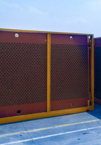
The H-type economizer, with its ribbed structure, exhibits improved resistance to ash accumulation compared to steel tube economizers. In a simulation conducted by Yang Dazhe using Fluent software, the flow field vector diagram of the H-type boiler economizer revealed that the fins of the economizer contribute to a more uniform airflow. The airflow, guided by the fins, laterally scours the tube, creating disturbances that effectively reduce ash buildup on the tube’s rear side. The H-type boiler economizer offers numerous advantages, extending its application beyond power station boilers to include increasingly widespread use in industrial boilers.

3. Boiler Heating Surface Design
In order to address the substantial power consumption of fans, pumps, and other equipment, a thermal power company has devised a plan to construct a new steam boiler for self-power generation. The desired evaporation capacity of the boiler is estimated at 140 t/h, and the designated model for this project is the SHW140-1.6/300-H Superheated steam boiler. Given the existing boiler room constraints, only one available space remains for the installation of the new boiler. Careful consideration must be given to avoid obstacles such as columns, structural beams, and inlet/outlet pipes within the boiler room. Taking into account the available space, the column spacing measures 21 meters by 12 meters. Additionally, the boiler design must incorporate provisions for SCR denitrification, requiring a dedicated space that accommodates a two-layer catalyst. This denitrification area should commence from the outlet of the boiler’s convection tube bundle, extend through the uniform flow grid, and leave approximately 9 meters of space in the tail flue.
The design of the boiler steel frame was meticulously executed to optimize the utilization of space within the boiler room, taking into account its height. The planned boiler steel frame consists of 16 columns, with a height of 19.26 m, and includes a small column situated in front of the grate. Of the 16 columns, 8 are symmetrically arranged from left to right. The spacing between the columns on either side of the boiler measures 3.24 m, while the gap between the columns in the tail flue area is 3.23 m. Previous design experience indicates that the flue gas temperature at the outlet of the convection bundle typically ranges between 200 to 300℃. However, this temperature range falls short of the desired 300 to 450℃ range necessary for SCR catalyst denitrification. To rectify this issue, it becomes imperative to reconfigure the convection heating surface and reduce the area of the convection bundle. These adjustments aim to align the temperature range of the flue gas at the outlet of the convection bundle with the requirements for SCR denitrification.
To create additional space for the tail height, it is proposed to relocate the outlet of the convection tube bundle to the upper surface of the upper pot barrel. This adjustment allows for an upward shift and provides an opportunity to cover the lugs on the side of the pot barrel with pouring material, preventing overheating and ensuring the integrity of the hanging strength. By implementing this change, the original tail height space is augmented by approximately 1.3 m, allowing for increased allocation of space for the heat receiving surface. With the inclusion of space reserved for SCR denitrification, the available area for the tail heating surface reaches approximately 8 m. Given the elevated temperature of the steam boiler return water, which reaches 104°C, it becomes imperative to incorporate an air preheater into the tail heating surface to facilitate heat transfer.
Considering that the boiler operates under various load conditions, including under-full load operation, it is essential to ensure that the flue gas temperature at the convection bundle outlet remains within the required temperature range for the catalyst. Therefore, during the thermal calculation and design of the boiler, the design value for the convection bundle outlet flue gas temperature should exceed the minimum catalyst temperature requirement by a certain percentage. This ensures that even during operation at 60% load, the temperature range necessary for denitrification can still be met. By incorporating this design consideration, the boiler can maintain optimal performance across a range of operating conditions.
In order to enhance the tail heating surface design, a thorough comparison and calculation of different arrangements for the tail heating surface have been conducted. By analyzing the actual data and comparing the results, the advantages of the H-type boiler economizer are evaluated. This optimization process aims to identify the most efficient and effective scheme for the tail heating surface, taking into consideration the practical data and performance analysis of the H-type boiler economizer.
(1) Tail heating surface scheme one: The heating surface arrangement involves combining a steel pipe economizer and an air preheater. The calculation of the convection tube bundle heating surface is based on an outlet flue gas temperature of approximately 400°C. The steel pipe economizer and air preheater are positioned at the end of the arrangement. For an exhaust temperature of 137°C, the steel pipe boiler economizer needs to be arranged in three stages, with each stage consisting of 16 rows of longitudinal pipes. The straight pipe length of the boiler economizer is 4.8 m, and the heat transfer area for each stage is 752.35 m2. The inlet water temperature is 104°C, while the lower, middle, and upper boiler economizer outlet water temperatures are 120.7°C, 144.9°C, and 180.3°C, respectively. The average flue gas flow velocities for the upper, middle, and lower boiler economizers are 7.29 m/s, 6.44 m/s, and 6.44 m/s, respectively.
The air preheater is composed of Φ40 mm×1.5 mm high weatherproof steel tubes with a length of 1.6 m. The average flue gas flow velocity is 11.4 m/s, the average air flow velocity is 8 m/s, and the water velocity inside the tube is approximately 0.93 m/s. The estimated total mass of a single boiler economizer tube is around 60 t.
Considering the heating surface calculation for the tail shaft arrangement, the height of a single-level economizer is 1.35 m. Thus, the total height of the three-stage economizer is 1.35 × 3 = 4.05 m. The air preheater tube has a length of 1.6 m, requiring a net space of 5.65 m for a single heating surface. Four maintenance spaces need to be allocated for the three-stage economizer, air preheater, and air preheater exit flue. However, these maintenance spaces, with an average height of about 0.5 m, are insufficient to meet the requirements for maintenance and ash cleaning for each heating surface.
An alternative approach is to punch holes beneath the air preheater on the foundation plane and direct the flue through the hole, with the air preheater positioned at the foundation steel frame column foot. While this plan provides more maintenance space, it still falls short in terms of ash cleaning for the air preheater tubes. Additionally, connecting the flue to the bottom of the operation platform requires reconnection to the total flue on the platform, leading to increased costs and poor technical and economic feasibility.
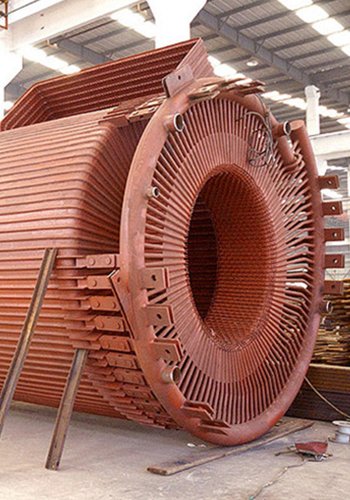
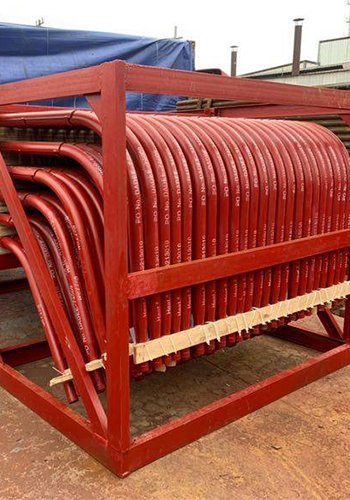
(2) Tail heating surface option two: The heating surface arrangement involves combining an H-type boiler economizer and an air preheater. In the calculation of the heat transfer area for the H-type boiler economizer, both the rib planes and the thickness direction of the side need to be considered simultaneously. The design of the H-type economizer is arranged horizontally, with a length of 4 m for each individual tube. The tube’s elbow is positioned outside the flue and is not included in the calculation to prevent wear and tear.
Based on a exhaust temperature of 142°C, the H-type boiler economizer only requires a two-stage arrangement. The number of longitudinal pipe rows for the upper and lower stages is 14 and 12, respectively. The heat exchange area for the two stages is 1,824 m2 and 1,564 m2, respectively. The inlet water temperature is 104°C, the outlet water temperature of the lower stage boiler economizer is 130.6°C, and the outlet water temperature of the upper stage boiler economizer is 184.9°C. The average flue gas flow velocities for the upper and lower stages of the boiler economizer are 8.34 m/s and 7.05 m/s, respectively.
The air preheater tube selected is Φ50×1.5 mm high weatherproof steel pipe with a length of 1.8 m. The average flue gas flow velocity is 11.6 m/s, and the average air flow velocity is 9.6 m/s. Considering the possibility of pressure differences at the exit collector of the boiler economizer during actual operation, the water flow rate in the governor tube is increased to prevent the water temperature inside the tube from reaching saturation or generating bubbles, which could result in a decline in heat transfer performance. The estimated total weight of the H-type economizer tube is around 49 t.
Considering the calculated arrangement of the heating surface in the tail shaft, the height of the two-stage economizer is 1.284 m and 1.1 m, respectively. The total height of the two-stage economizer is 2.384 m. The length of the air preheater tube is 1.8 m, and a single heating surface requires approximately 4 m of clear space. Three service spaces need to be reserved for the two-stage economizer, air preheater, and air preheater outlet flue. The average height of each service space is 1.3 m, providing sufficient space for maintenance and ash cleaning of each heating surface.
(3) Analysis of Calculation Results:
When comparing the H-type boiler economizer with the steel tube economizer, it is evident that the H-type economizer reduces one stage, resulting in a lower total weight of the tubes. The single tube weight for H-type boiler economizer is approximately 49 t, whereas it reaches about 60 t for the steel tube economizer. Additionally, the H-type boiler economizer eliminates two intermediate collectors when compared to the three-stage steel tube economizer.
Furthermore, the H-type boiler economizer requires fewer supporting steel beams compared to the three-stage steel tube economizer. This indicates that the H-type boiler economizer utilizes less material while still meeting the required heating surface area, resulting in better technical economy.
The unique rib arrangement structure of the H-type boiler economizer naturally divides the flue gas into multiple parallel flue channels, which performs a similar function to that of a rectifier grille. This design feature enhances the efficiency and effectiveness of the H-type boiler economizer.

With the growing emphasis on environmental regulations for boiler flue gas emissions, the inclusion of SCR denitrification space has become a prerequisite for new industrial boilers and retrofit projects. The H-type economizer offers numerous benefits, including a substantial extended surface area, excellent wear resistance, and minimal ash accumulation. When combined with properly arranged heat exchange components like air preheaters, the H-type economizer proves to be a superior option in terms of both technical performance and economic viability. As a result, its adoption in industrial boiler applications is steadily expanding to meet the increasing demand for efficient and environmentally friendly solutions.
[Source] Guo ruiqing,No.6,2022 Modern Industrial Economy and Informationization
Ready to supercharge your industrial boiler performance? Explore the power of H-Type Coal Economizer today and unleash its game-changing advantages!