In recent years, due to the increasing stringency of national environmental protection requirements, the emission standards for nitrogen oxides (NOx) from coal-fired power plants have significantly improved. Currently, the primary methods employed for denitrification in these plants are selective catalytic reduction (SCR) and non-selective catalytic reduction (SNCR). During the denitrification process, both SCR and SNCR methods involve the injection of substantial quantities of urea or ammonia into the flue gas pipeline. As a result, a notable portion of the ammonia volatilizes and is discharged along with the flue gas. This unreacted ammonia can potentially react with sulfur trioxide in the flue gas, leading to the formation of ammonium bisulfate (ABS).
The presence of ammonium bisulfate in the flue gas causes it to adhere to the fly ash, resulting in deposition on downstream equipment and piping. Consequently, the boiler tail system becomes susceptible to issues such as clogging, corrosion, and increased resistance. Moreover, the combination of flue gas and water vapor produces sulfuric acid vapor, which tends to condense on low-temperature metal surfaces. This condensation leads to dew-point corrosion when the sulfuric acid reacts with alkaline ash in an acid-base reaction or corrodes the walls of metal pipes.
This study focuses on investigating the corrosion phenomenon occurring in the low-temperature boiler economizer of a 220t/h high-pressure coal-fired boiler that utilizes SNCR denitrification. The corroded tubes are thoroughly examined and analyzed using advanced techniques such as scanning electron microscopy (SEM), energy spectroscopy (EDS), and X-ray diffraction (XRD). The obtained results are utilized to explore the distinctive characteristics of the corrosion failures observed in the boiler economizer.
Test samples and Methods
To analyze the corrosion and scaling failure in the disassembled boiler economizer tube bundle, 10mm x 10mm specimens were obtained using wire cutting equipment. These specimens were fixed using epoxy resin. Subsequently, the specimens were subjected to a series of sanding and polishing steps using sandpaper with grit sizes of 400, 600, 800, 1000, and 2000, followed by polishing using a polishing machine.
The physical composition of the corrosion products and scale samples was determined using a Rigaku D/MAX-RB X-ray diffractometer. The analysis was performed under specific conditions, including Kα irradiation of a copper (Cu) target and an operating voltage of 40 kV. This X-ray diffraction technique allowed for the identification of the crystalline phases and chemical composition of the corrosion products and scales.
Furthermore, the micro-morphology of different areas of the specimens was observed using a Shimadzu SSX-550 scanning electron microscope (SEM)/EDS. The SEM provided high-resolution images of the specimen surfaces, while the energy spectrometry analysis enabled the elemental composition analysis of different regions within the specimens.
These advanced techniques were employed to gain insights into the physical composition, crystalline structure, and micro-morphology of the corrosion products and scales, aiding in the understanding of the corrosion and scaling failure in the economizer tube bundle of the disassembled boiler.
Results and Discussion
Boiler economizer sample tube microscopic morphology and element distribution
Figure 1 displays the SEM morphology of the specimen, illustrating the layers present from point a to point b, namely the base material, corrosion product layer, and scale layer. Additionally, Figure 2 presents the results of an elemental line scan conducted from point a to point b on the boiler economizer sample.
Based on the observations from Figure 2, the following can be inferred:
- In the section ranging from 0 to 340 μm, the mass fraction of the Fe element exceeds 99%, while the other elements are essentially negligible. This suggests that this section represents the matrix section of the pipe wall.
- In the section spanning from 340 to 430 μm, the mass fraction of the Fe element sharply decreases but stabilizes above 33%. Simultaneously, the mass fractions of O and S elements significantly increase to 45% and 8%, respectively. Occasional small peaks of Ca, Si, and N elements are observed, making it challenging to determine their exact presence state. Other elements show minimal variations. It can be inferred that this section corresponds to the corrosion product layer of the sample tube, with evidence supporting the involvement of S elements in the corrosion process of the sample tube substrate.
- Beyond 430 μm, the mass fraction of the Fe element experiences a rapid decrease, while all other elements exhibit a sharp decline. The composition in this section becomes noticeably diversified. Notably, the mass fractions of O and S elements continue to increase and stabilize at around 60% and 20%, respectively. The mass fractions of Ca, Si, and N elements, which appear for the first time, rapidly increase. Calcium (Ca) and silicon (Si) elements persist consistently throughout the scaling layer. Therefore, it can be assumed that this section represents a scaling layer. However, the mass fraction of nitrogen (N) elements intermittently reaches zero, indicating that the presence of N elements is not continuous and homogeneous.


Boiler economizer sample tube corrosion layer and scale layer product phase
The SEM line scan analysis of the boiler economizer sample tube reveals significant variations in elemental content along the surface of the outer wall. To further validate the SEM findings and ascertain the specific composition of the corrosion and scaling layers, samples were extracted from different layers of the outer wall of the boiler economizer sample tube. These layers are denoted as A, B, C, and D, representing the innermost to the outermost sections of the outer wall substrate. The results of this analysis are depicted in Figure 3. Additionally, the results of X-ray diffraction (XRD) tests conducted on the samples are presented in the same figure.
Please note that the information regarding the specific results and interpretation of the SEM and XRD tests in Figure 3 needs to be provided or uploaded in order for me to assist in describing the findings accurately.
The XRD results of samples taken from different areas of the outer wall of the boiler economizer sample tube indicate the predominant components present in each layer. The inner layers A and B primarily consist of Fe2O3, CaSO4, SiO2, Fe(NH4)2(SO4)2-6H2O, and (NH4)2SO4. On the other hand, the outer layers C and D are mainly composed of CaSO4, SiO2, Fe(NH4)2(SO4)2-6H2O, and (NH4)2SO4.
Interestingly, the inner layers A and B exhibit a higher proportion of the Fe2O3 phase compared to the outer layers. This suggests that the corrosion process in the inner layers may have resulted in the formation of a greater amount of Fe2O3. The presence of Fe2O3, along with other compounds such as CaSO4, SiO2, Fe(NH4)2(SO4)2-6H2O, and (NH4)2SO4, highlights the complex nature of the corrosion and scaling layers present in the outer wall of the boiler economizer sample tube.
These findings from the XRD analysis provide valuable insights into the specific composition of different layers within the outer wall of the boiler economizer sample tube, shedding light on the materials involved in the corrosion and scaling processes.
From the observation of Figure 3, it is evident that the Fe2O3 diffraction peaks are strongest in the innermost layer A, followed by a rapid decrease in the B layer, and complete absence in the outer layers C and D. This pattern aligns with the trend observed for the Fe element in the SEM line scan presented in Figure 2. The disappearance of Fe2O3 diffraction peaks in the outer layers C and D is consistent with the absence of Fe in the scaling layer shown in the SEM analysis.
The results suggest that oxygen diffusion, likely facilitated through the scaling layer of the pipe wall, and a redox reaction with the metal wall contribute to the formation of iron oxides, specifically Fe2O3. The research conducted by Ma Shuangzhen also supports the notion that NH4HSO4 corrosion of metals can lead to the production of Fe2O3.
Considering the analysis results of the elemental line scanning and the XRD analysis, it can be concluded that the A layer represents the corrosion layer, with Fe2O3 being the primary corrosion product. The B layer serves as a transition zone between the corrosion layer and the scaling layer. Finally, the C and D layers correspond to the scaling layer.
This comprehensive understanding of the different layers provides valuable insights into the corrosion and scaling processes occurring within the outer wall of the boiler economizer sample tube.
Fe(NH4)2(SO4)2-6H2O is present in various parts of the flue gas due to acid dew point corrosion, corrosion of the pipe wall by NH4HSO4, and reactions between these compounds and iron oxides present in fly ash. As the flue gas temperature decreases, the SO3 in the flue gas combines with water vapor to form sulfuric acid vapor. As the flue gas flows and further cools, reaching the dew point of sulfuric acid, sulfuric acid vapor gradually condenses on the boiler economizer tube wall, resulting in low-temperature sulfuric acid dew-point corrosion and the formation of FeSO4.
Literature highlights the similarity between the corrosion process of NH4HSO4 and sulfuric acid solution on carbon steel, with the resulting corrosion product containing iron sulfate. This FeSO4, along with water vapor, NH4HSO4, and iron oxides in fly ash, react to form Fe(NH4)2(SO4)2-6H2O2O. Consequently, Fe(NH4)2(SO4)2-6H2O becomes a major component in the B, C, and D layers.
It is important to note that the intensity of sulfuric acid low-temperature acid dew point corrosion and NH4HSO4 corrosion on the pipe wall is more pronounced in the early stages of the corrosion reaction. As ash accumulates and undergoes filtration and alkaline oxides neutralization, the intensity of sulfuric acid and NH4HSO4 corrosion decreases. Meanwhile, oxygen in the flue gas continues to diffuse to the surface of the metal pipeline, initiating redox reactions and causing the corrosion product layer to thicken. Consequently, as the corrosion product layer thickens, the relative content of S elements in the layer decreases. This explains why the S element content is lower in the 340-430 μm section of the elemental line scan, followed by a relatively stable S element content.
Based on the XRD results of layer A and the elemental content of the corrosion product layer observed in the elemental line scanning, it can be deduced that the presence of CaSO4 and SiO2 in the XRD results of layer A is likely due to the introduction of fouling layer components during the sampling process. The diffraction peaks of SiO2 in each part do not exhibit significant changes since SiO2 is an acidic oxide that does not actively participate in the corrosion and oxidation processes. Its presence is mainly associated with the composition of ash present in the flue gas, resulting in relatively uniform SiO2 content.
The formation of CaSO4 can be attributed to the reaction between the CaO present in the fly ash and sulfuric acid vapors and ammonia hydrogensulfate droplets. This reaction leads to the production of CaSO4 as a component of the corrosion product layer.
It is important to consider the potential influence of sampling precision on the presence of certain components in layer A, as it could introduce additional materials not directly related to the corrosion and scaling processes under investigation.

The complicated diffraction peaks of (NH4)2SO4 in each layer indicate that its content distribution is not uniform. This observation aligns with the changing pattern of the N element in the SEM line scan shown in Figure 2. The irregular distribution of (NH4)2SO4 is likely related to the varying state of NH4HSO4 in the flue gas.
NH4HSO4 has a melting point of 147°C and is dispersed in the flue gas as droplets within the temperature range of the boiler economizer. This dispersion leads to corrosion and ash accumulation on the outer wall of the boiler economizer pipeline. Consequently, NH4HSO4 does not exist in a continuous and homogeneous state during the corrosion of the outer wall of the boiler economizer pipe and the formation of ash accumulation.
The non-uniform distribution of (NH4)2SO4, as indicated by the complicated diffraction peaks, reflects the heterogeneous nature of NH4HSO4 in the flue gas and its involvement in the corrosion and scaling processes.
The escape of ammonia from the flue gas injected into the SNCR system of the boiler results in reactions with SO3 in the flue gas, leading to the formation of NH4HSO4 and (NH4)2SO4. While (NH4)2SO4 can be directly generated, research indicates that the formation rate of NH4HSO4 is significantly higher than that of (NH4)2SO4. Consequently, the amount of NH4HSO4 generated is much greater in practical production processes.
Interestingly, NH4HSO4 and (NH4)2SO4 were not detected in the XRD analysis of all the layers of the outer wall of the boiler economizer sample tube. This lack of detection is likely due to the interaction between NH4HSO4 and the flue gas. NH4HSO4 can react with NH3 in the flue gas, CaO in fly ash, Fe2O3 in fly ash, or corrosion products to form (NH4)2SO4, CaSO4, FeSO4, and other compounds. The majority of the (NH4)2SO4 detected by XRD is likely formed through the reaction of NH4HSO4. The distribution of these characteristics on the outer wall of the boiler economizer tube is also influenced by these interactions.
In summary, the corrosion failure of the boiler economizer tube is a result of the combined effects of oxygen, sulfuric acid, and ammonium bisulfate. These factors interact and contribute to the corrosion process occurring within the boiler economizer tube.
Measures taken to prevent corrosion and ash accumulation on the heating surface at the tail end of the boiler and operational effects
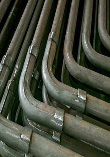
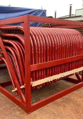
(1) Replacement of the heat exchanger ribs of the boiler economizer: In order to address the issue of severe ash accumulation on the ribs of the H-type heat exchanger tubes, a solution is implemented to reduce the contact surface area with the flue gas. This is achieved by replacing the H-type heat exchanger tubes with light tube fin heat exchanger tubes. The new design of the light tube fin heat exchanger tubes helps mitigate the problem of ash accumulation, leading to improved performance and efficiency.
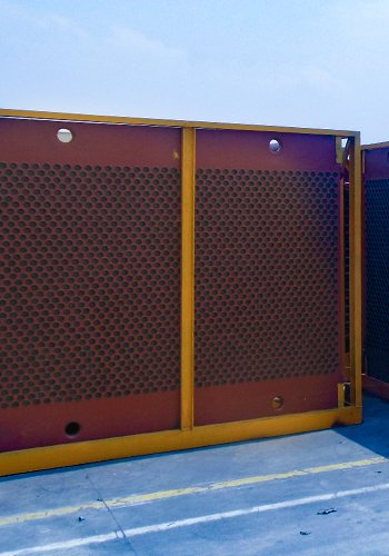
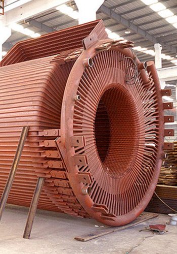
(2) Replacement of air preheater material: The original air preheater in the boiler, made of plain carbon steel, exhibited poor corrosion resistance, resulting in significant leakage within a short period of less than two years. To address this issue, the decision is made to replace the air preheater with corrosion-resistant ND steel. Additionally, advanced enameling technology is employed. A layer of 0.2mm enamel film is applied to the inner diameter of the air preheater tubes, enhancing their corrosion resistance. This enamel film acts as a protective barrier against corrosive elements, ensuring a longer lifespan and better performance of the air preheater.

(3) Increase flushing: An effective measure to mitigate ash accumulation is to install acoustic sootblowers in the lower part of the low-temperature boiler economizer and the upper part of the new light pipe boiler economizer tubes. These sootblowers are used to regularly blow off accumulated ash during boiler operation. Additionally, ensuring the quality of manual soot cleaning is important. Regular inspections and cleaning of the boiler economizer are performed to ensure there is no ash accumulation and that the light tubes are visible, promoting optimal heat transfer and reducing the risk of corrosion and fouling.
(4) Reduce urea injection and ammonia escape: To address excessive ammonia escape and corrosive material generation, operational and control adjustments are implemented. The arrangement of the urea spray guns is modified to reduce ammonia escape. The original arrangement, consisting of 16 rods located in the front wall of the boiler chamber, is altered. Additional lances are added to the side walls of the boiler, while four lances are removed from the front wall. A new type of urea nozzle is used to achieve even distribution of urea in the combustion chamber. These modifications result in a more uniform distribution of urea and a decrease in the overall amount of sprayed urea, effectively reducing ammonia escape.
(5) Impact of corrosion and ash accumulation prevention measures on the heating surface: The implemented measures significantly reduce pipe bursting accidents on the heating surface at the tail of the boiler. Through a year of production and operation, with stable parameters of the steam pipe network and the boiler operating at rated load, the number of pipe bursts in one year (January to December 2019) after the transformation decreases by nine times compared to the period from November 2017 to October 2018. Moreover, the power generation capacity is increased by 11,742 MWh. This demonstrates the effectiveness of the implemented corrosion and ash accumulation prevention measures, resulting in improved operational stability, reduced maintenance incidents, and increased power generation capacity.
Conclude
To summarize:
(1) The elemental line scan results indicate that the corrosion layer on the outer wall of the boiler economizer tube in the SNCR coal-fired boiler has a thickness of approximately 90 μm. The main elements detected in this layer are Fe, S, and O.
(2) A comprehensive analysis of the elemental line scan and XRD results reveals that the corrosion layer on the outer wall of the boiler economizer tube primarily consists of Fe2O3 and Fe(NH4)2(SO4)2-6H2O. On the other hand, the scaling layer predominantly contains CaSO4, SiO2, Fe(NH4)2(SO4)2-6H2O, and (NH4)2SO4.
(3) The corrosion failure of the SNCR coal-fired boiler economizer tube is a result of the coupled effects of oxygen, sulfuric acid, and ammonium bisulfate.
(4) Implementation of various measures such as using light tube fins heat exchanger tubes, utilizing ND steel pipes coated with enamel film, increasing the frequency of flushing for ash removal, and reducing the amount of urea injection can effectively reduce corrosion, minimize ash accumulation, and decrease the occurrence of pipe bursts on the heating surface of the boiler tail.
[Source] Li Congkang, Jia Lidi , Wang Dongshan , Zhang Tianfu , He Song , Liu Baihan , Sun Liang (1. Energy Management Centre of Angang Company Limited, Anshan 114002, China; 2. The General Iron Plant of Angang Steel Company Limited, Anshan 114021, China)
Ready to Enhance Your Boiler Economizer? Learn Proven Strategies to Combat Corrosion and Minimize Ash. Get Started Today!