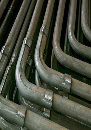
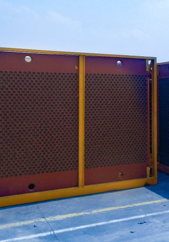
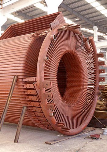
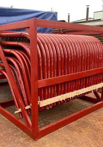
In 2022, we stumbled upon a rather concerning issue during our C-level maintenance of a power plant. We found a significant amount of high-temperature corrosion in the boiler water walls. The corrosion was primarily concentrated in the region between the main combustion zone and the exhaust air from combustion, displaying all the classic signs of high-temperature corrosion.
This corrosion dilemma led to a precarious situation, with some of the boiler water wall pipes having a remaining wall thickness of less than 4.85mm. To be exact, 197 pipes were affected by this corrosion, with 87 in the front wall and 110 in the back wall. Luckily, the right and left walls remained unscathed.
Upon closer investigation and careful analysis, we uncovered the root causes behind this troubling corrosion. Firstly, we identified issues with the combustion process within the furnace. Poor combustion organization had led to flames brushing against the walls, creating an oxygen-deficient environment in the main combustion zone. This oxygen deficiency, in turn, fostered a reducing atmosphere, which played a pivotal role in the high-temperature corrosion. Another significant contributor was the use of high-sulfur coal, which exacerbated the corrosion problem.
Furthermore, our investigation revealed that the secondary air differential pressure was too low. This resulted in a reduced volume of secondary air reaching the main burner area, weakening the effectiveness of “wind packet powder” combustion. This not only increased the risk of flames brushing against the walls but also contributed to the boiler water wall being exposed to the reducing atmosphere.
In summary, our encounter with high-temperature corrosion in the boiler water walls of the power plant in 2022 was a wakeup call. We identified poor combustion organization, an oxygen-deficient main combustion zone, and the use of high-sulfur coal as the primary culprits behind this issue. Additionally, the insufficient secondary air pressure further exacerbated the problem. Addressing these issues promptly became crucial to ensure the long-term performance and safety of the power plant.
Let’s make this inspection report more reader-friendly:
Boiler Water Wall Inspection
1. Boiler Water Wall Coking and Corrosion Inspection
Our power plant has a total of 1110 boiler water wall tubes. Out of these, 92 tubes have been excluded due to burner cut corners. We divided the remaining 1018 tubes into different sections: 277 in the front and rear walls, and 232 in the left and right walls. While most of the boiler water wall sections showed no signs of corrosion, we did find coking in certain areas. Here’s a breakdown:
(1) Front Wall Coking: We discovered extensive coking on the front wall of the furnace. This coking stretched from the A layer down to the lower level of the exhaust air layer. In total, we found 87 coking locations in this area. The coking reached a height of 14 meters, had a width of 5.5 meters, and covered an area of 77 square meters.
(2) Back Wall Coking: The back wall of the furnace also had a significant area affected by coking. The coking here extended from the B layer to the higher level of the exhaust air layer. We identified 110 coking positions in this region, with a coking height of 12 meters, a width of 7 meters, and a total coking area of 84 square meters.
(3) Left Wall: Fortunately, there was no coking observed on the left wall of the furnace.
(4) Right Wall Coking: While not as extensive as the front and back walls, we did find some coking on the right wall of the furnace. The coking spanned from the F layer to the OFA2 layer and was limited to 47 positions. The height of the coking was 2 meters, with a width of 3 meters, and it covered an area of 6 square meters.
This inspection provides us with valuable insights into the condition of our boiler water walls, highlighting the areas where coking and corrosion are present and warranting further attention and maintenance.
Analysis of corrosion causes
2.1 Influence of Furnace Cut Corners
High-temperature corrosion is a result of two main conditions: elevated temperatures within the furnace and the presence of a reducing atmosphere. Examining the locations where coking and corrosion were most pronounced, we found that the most severe high-temperature corrosion occurred in the region between the primary combustion zone and the combustion wind—a zone with the lowest oxygen levels. This area essentially belongs to the boiler’s combustion reduction zone.
Analyzing the patterns of coking and corrosion, it became evident that coking predominantly occurred on the front and rear walls. More specifically, coking was concentrated near the first corner of the front wall and the third corner of the rear wall. Remarkably, there was no corrosion thinning observed in areas of the boiler water wall without coking. Upon removing the coke build-up, we discovered unburned coal particles. This indicated that the furnace tangent circle was misaligned, leading to flames brushing against the walls. This, in turn, caused molten coal ash or unburned coal dust to come into contact with the boiler water wall. The rapid temperature reduction caused these particles to adhere to the boiler water wall, forming slag. The distribution of coking and high-temperature corrosion highlighted a complementary relationship between the two, emphasizing the significant influence of combustion organization within the furnace.
2.2 Impact of Operational Modes on High-Temperature Corrosion
In analyzing the operational modes between 2018 and 2022, it was apparent that the operation mode remained consistent during this period. For loads up to 330MW, we employed the operation mode utilizing the lower four mills. For the range of 330MW to 430MW, we utilized the lower five mills, and for loads exceeding 430MW, the operation mode involved all six mills. No significant changes occurred in the operation mode between 2018 and 2022.
Concerning furnace No. 4, we employed the classic girdle-shaped wind distribution mode for wind distribution. This involved large upper and lower secondary air doors and smaller middle layers, with peripheral winds fully closed. Secondary air box pressure control was maintained at specific levels: 0.7kPa to 0.8kPa for 600MW, 0.5kPa to 0.6kPa for 450MW, and 0.3kPa to 0.4kPa for 300MW.
However, due to the deterioration of coal quality, we observed an increase in the primary air rate percentage and a decrease in the secondary air rate from 2020 to 2022. Consequently, the secondary air box pressure steadily declined. To compensate and maintain the required pressure, we progressively closed down each secondary small air door. As the differential pressure of the secondary air decreased, the volume of secondary air reaching the main burner area reduced. This weakening effectuated a decrease in the efficacy of “wind-packed powder” combustion and, subsequently, a diminished protection of the boiler water wall by the secondary air.
These operational nuances, as we’ve outlined, have a direct impact on high-temperature corrosion within the furnace, underscoring the importance of monitoring and adjusting operational parameters for the sake of maintaining equipment integrity and performance.
Solution Measures
3.1 Ensuring Burner Efficiency
To address the issue of declining secondary air box pressure, we’ll start by conducting a comprehensive check of the burner-related components. This will include inspecting the cold wind door baffle, baffle openings, external markings, and DCS (Distributed Control System) opening values. By scrutinizing these elements, we can identify any factors contributing to the decrease in secondary air box pressure and address them promptly.
3.2 Pulverized Coal Separator Assessment
We will conduct a thorough examination of the pulverized coal separator to ensure its optimal functioning. This assessment will encompass checking the uniformity of the openings of the pulverized coal fineness adjusting baffle and verifying the integrity of the primary air duct entrance partition within the separator. Our aim is to prevent significant deviations in the distribution of pulverized coal in the primary air duct, which can lead to the creation of a strong reducing atmosphere near the furnace wall.
3.3 Prioritizing Burner Inspection During Overhaul
During scheduled overhauls, we will place a strong emphasis on burner inspection. Any issues such as nozzle deformation, settlement, or blockage will be addressed promptly. Additionally, we will review the correct installation angle (angle of cut) of the burners. Ensuring the alignment of the furnace power field and primary wind speed thermal adjustments will be crucial to maintain optimal combustion efficiency.
3.4 Enhanced Boiler Water Wall Maintenance Management
We recognize the importance of robust maintenance practices for our boiler water walls. Utilizing unit shutdowns and maintenance windows, we will focus on conducting thorough heated surface tube anti-wear and explosion-proof inspections. We’ll also implement a rigorous tracking and monitoring system to stay vigilant against high-temperature corrosion in the boiler water walls.
By implementing these measures, we aim to enhance the overall performance and reliability of our power plant while addressing the specific challenges related to combustion, pulverized coal distribution, burner efficiency, and boiler water wall maintenance. These steps will contribute to the long-term sustainability and safety of our operations.
Analysis and Conclusion
In our investigation, we identified several critical factors contributing to the high-temperature corrosion observed in our power plant’s boiler water walls. These factors are central to understanding and mitigating the issue:
1. Poor Furnace Combustion Organization: One of the primary contributors to high-temperature corrosion is the inadequate organization of combustion within the furnace. This poor combustion organization leads to flames brushing against the walls and, as a consequence, results in an oxygen-deficient main combustion zone. This oxygen deficiency creates a reducing atmosphere, which significantly contributes to the high-temperature corrosion. Additionally, the blending of high-sulfur coal exacerbates the corrosion problem, making it a key factor.
2. Insufficient Secondary Air Differential Pressure: Another significant factor is the insufficient differential pressure of the secondary air. This limitation reduces the volume of secondary air reaching the main combustion area, thereby weakening the effectiveness of “wind-packed powder” combustion. As a result, there is an increased risk of flames brushing against the walls, and this further exacerbates the problem of high-temperature corrosion. It also leads to an increase in the reducing atmosphere surrounding the boiler water walls.
In conclusion, the high-temperature corrosion of our boiler water walls is a complex issue with multiple contributing factors. To address this problem effectively, it is imperative that we take immediate action to improve combustion organization within the furnace. Additionally, careful monitoring and adjustments of secondary air pressure and distribution are essential to maintain the protective atmosphere around the boiler water walls. Lastly, we must remain vigilant in our efforts to manage the quality of coal used in our operations to mitigate the impact of sulfur content on corrosion. By addressing these key factors, we can enhance the performance, longevity, and safety of our power plant operations.
DHB Boiler
Discover The Superior Quality And Cutting-Edge Technology Of DHB Boilers. Explore Our Range Of Biomass Boilers, Waste Heat Boilers, And More. Take Your Industrial Operations To New Heights With DHB Boiler.
