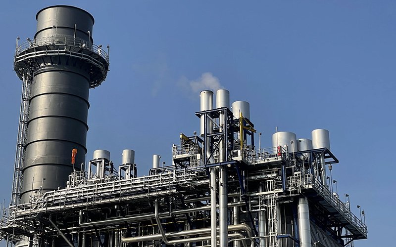
In the realm of industrial engineering and energy systems, the efficient design and operation of a boiler superheater are paramount. Understanding the intricacies of boiler superheater piping, from its meticulous arrangement to stress analysis, can significantly impact the overall performance and safety of these vital systems. In this discussion, we delve into the world of boiler superheaters, examining their piping arrangement and stress analysis, offering insights into achieving optimal design and functionality.
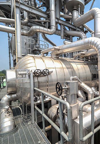
The boiler system comprises numerous pipes, both big and small, with intricate designs. These include four major pipelines: the startup system piping, desuperheating water piping, accidental water discharge piping, and various measuring point piping, among others. Each of these pipes serves a distinct and crucial purpose. It’s safe to say that when it comes to the overall design of the boiler, piping design plays a significant role. In this discussion, we will primarily focus on the layout and stress analysis of the boiler’s superheater desuperheating spray pipe.

Overall Piping Arrangement of Superheater
2.1 Piping arrangement
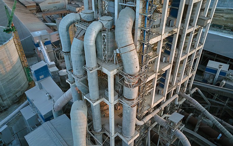
When it comes to arranging the piping in the boiler system, there are a few key steps to follow. First and foremost, we need to review the technical agreement and determine whether there are any specific requirements or design scopes for the piping. This helps us establish the starting point and end interface location of the pipeline. We also take into account the boiler diagram to get a general sense of the pipeline direction before proceeding with the layout.
For the superheater desuperheater spray pipe, we typically start from the interface location of the boiler water pipeline and end at the location of the boiler’s superheater spray water desuperheater nozzle. Therefore, it’s essential to clarify the position where the superheater temperature reduction spray pipe interfaces with the feed pipe and the specific location of the superheater water spray desuperheater within the boiler. If the boiler feed pipe falls under the design institute’s scope of supply, cooperation with the design institute is necessary to determine the interface position of the superheater water jet pipe.
Since the design of the boiler water supply pipeline is calculated by the design institute and the superheater cooling spray pipe has a relatively large diameter, we usually place a fixed point ahead of the gate valve in the main pipe. The fixed point downstream of the pipeline is responsible only for layout, with calculations jointly conducted by the design institute for both the water supply pipeline and the fixed point. The data determined at the fixed point is based on vector superposition of the calculation results upstream and downstream of the node.
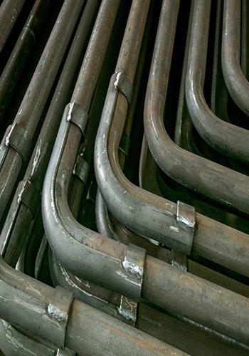
During the layout process, we must take into consideration factors such as the thickness of pipe insulation, the direction of thermal displacement, and the need to avoid obstructions like steel frame columns, horizontal beams, diagonal braces, node plates, and other elements related to boiler body piping and the design institute’s piping. Additionally, we aim to maintain a reasonable clearance between the piping and various boiler equipment and attachments. For ease of workshop manufacturing, in the absence of specific project provisions, superheater desuperheater spray pipes are generally designed as straight pipes with elbow and tee components.
2.2 Arrangement of valves and other devices
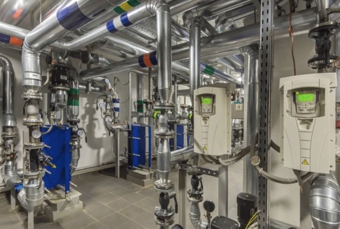
When it comes to arranging valves and other devices along the pipeline, it’s important to consider the various control valves, temperature and pressure measuring devices, and flow devices that are part of the system. According to the “Thermal Power Plant Steam and Water Piping Design Technical Regulations” (referred to as the “Pipe Regulations”), valves should be placed in locations that facilitate easy operation, maintenance, and repair, preferably on a platform. For heavy-duty valves and larger welded valves, it’s suitable to position them on horizontal pipelines.
In the case of superheater desuperheating spray piping, which typically includes regulating valves, gate valves, check valves, flow meters, and other devices, it’s common practice to arrange these valves centrally at the same level as the steel frame—usually on the operating platform. The layout of the operating platform must also adhere to the provisions of the Pipe Regulations, ensuring that it allows for convenient operation, maintenance, and overhaul, while also providing sufficient space for the valves. Therefore, before proceeding with pipeline arrangement, it’s essential to clarify the number of valves required for the pipeline and determine their specific order of arrangement.
The “Pipe Regulation” also specifies that if a pipeline is equipped with a flow measurement device, such as a measuring orifice plate, there should be a certain length of straight pipe section both before and after the device. The length of this straight pipe section can be determined from the technical performance data of the flow device. It’s important to note that the minimum required length of straight pipe section before and after the flow device should not be used for the installation of other components like water pipes or receiver seats, as it can affect the accuracy of the measurements.
2.3 Arrangement of support hangers
When planning the direction of pipeline layout, it’s crucial to consider the arrangement of support hangers. These support hangers play a vital role in bearing the various loads that act on the pipeline, including dynamic loads, static loads, and unexpected loads. They also help constrain pipeline displacement in a reasonable manner, ensuring that pipeline stress remains within allowable limits under different operating conditions. The placement of support brackets should be strategically designed to distribute pipeline loads effectively, enhancing pipeline strength and stiffness, increasing system stability, preventing pipeline vibrations, and avoiding excessive secondary stress on the pipeline.
In the actual design process, it’s essential to take into account the specific steel frame structure and the location of support points. This includes considering the position of the support point relative to the root beam, allowing sufficient space for arranging springs, booms, necessary connections, and other components associated with the hanger and ensuring that hanger supports do not collide with other equipment. Additionally, the expansion direction and value of the entire pipeline system should be considered to prevent any interference between hot and cold states.
Furthermore, the overall working conditions of the entire pipeline system must be considered. It’s advisable to install support hangers in close proximity to centralized loads, such as valves and tees, to provide additional support and stability where needed. This comprehensive approach to support hanger arrangement ensures the safe and efficient operation of the pipeline system.

Stress Analysis of Pipeline
Before conducting a stress analysis calculation on the pipeline, it’s essential to establish the endpoints of the three-dimensional model for the pipeline and define the displacement values for each direction. In the case of superheater desuperheater nozzle piping, it’s customary to set these endpoints from the main gate valve to a fixed point, ensuring that the displacement in all three directions is zero. The displacement at the desuperheater nozzle can be determined either from the boiler expansion system diagram or calculated using appropriate formulas.
Once the pipeline is accurately modeled, it can be subjected to stress analysis using software like CAESAR II, which provides valuable insights into the stress distribution and potential areas of concern. Based on the results of the analysis, necessary modifications and optimizations can be made to the pipeline design to ensure that it operates safely and efficiently. This iterative process of analysis and refinement is crucial for maintaining the integrity of the pipeline system.