Large-capacity, high-parameter units have gained widespread acceptance as mainstream generating units owing to their notable advantages, such as low coal consumption, high operating efficiency, compact footprint, and minimal pollutant emissions. During the construction of these large generating units, special attention must be given to the installation of the boiler and its ancillary equipment, with particular emphasis on the boiler heating surface. The installation of the internal heating surface of the boiler presents significant challenges due to its substantial size, intricate structure, and the need to weld tubes composed of diverse materials. Furthermore, the design of the boiler may vary for units of the same capacity, based on the type of coal combustion employed, resulting in different installation requirements.
Hence, a thorough analysis of the force strength at the lifting points of the boiler heating surface and meticulous calculations for the lifting equipment’s strength are crucial to determine an appropriate and suitable installation process. In this paper, we will exemplify the installation of the heating surface in a 1000MW unit’s boiler as a practical case study.
Installation Process:
When it comes to the installation of the boiler heating surface, several critical considerations and lifting methods need to be taken into account. The water-cooled wall and steel frame of the boiler are typically lifted using a movable tower crane. On the other hand, the superheater, reheater, and economizer are lifted from the bottom up, with a dedicated lifting device positioned at the top of the boiler. This arrangement eliminates the need for individual lifting ports on the top or sides of the boiler.
However, the lifting access has a significant impact on the installation process, particularly for the boiler heating surface. Three well-established lifting methods for the heating surface are generally considered:
- Laying out the FHTT2800 flat-top tower crane in the center of the boiler furnace or on the side of a single boiler.
- Laying out the heating surface on the left side of the boiler furnace or on both sides of the boiler furnace using two jib cranes working in tandem.
- Utilizing a combination of a jib crane and a large-scale crawler crane for lifting.
In this particular project, certain factors need to be taken into account while selecting the appropriate lifting method. One of the primary concerns is the layout of the pulverized fuel silo, which must align with the lifting requirements of multiple components with large single-unit weights. The project aims to achieve a balance between saving land, reducing costs, and meeting the lifting demands.
Considering the arrangement requirements of the pulverized coal silo, the project adopts a layout of one jib tower crane at the front and one at the back of the boiler. This approach optimizes the installation process, ensuring efficient lifting operations while also providing benefits in terms of cost and land-saving measures.
Currently, the hoisting of the superheater, reheater, and economizer predominantly relies on the winch and monorail hoisting method. Although this approach offers certain advantages in terms of equipment searching and transferring, it necessitates multiple dismantling and assembly steps. This not only increases the workload but also escalates the construction costs. To address these challenges, the project has adopted a more efficient lifting strategy.
The project has implemented four winches equipped with an intelligent monitoring and synchronized lifting system for the hoisting process. The lifting of the heating surface is meticulously executed after the diaphragm wall has been precisely located and inspected. The intelligent monitoring system plays a crucial role by providing alarms and prompts. These warnings indicate whether the lifting components exceed the weight limits, whether they might collide with fixings, or if any potential obstacles are likely to obstruct the lifting pathway. This level of monitoring ensures that the lifting components are safely and steadily positioned at their designated locations.
By incorporating an integrated lifting process, the project enhances the efficiency of the installation. The sequence of vertical tandem lifting and horizontal inward lifting of the heating surface, as demonstrated in Fig. 1 and Fig. 2, serves two key purposes. Firstly, it improves the overall installation efficiency. Secondly, it reduces the wear and tear on the pipe wall, caused by fly ash particles present in the flue gas.
In summary, the implementation of four winches with intelligent monitoring and synchronized lifting, along with the adoption of an integrated lifting process, not only optimizes installation efficiency but also minimizes construction costs and ensures the safety and precision of the entire hoisting operation.

Installation of the Boiler Heating Surface
2.1 Installation of the Boiler Economizer
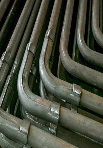
The boiler economizer is strategically positioned in the lower section of the boiler tail shaft and is divided into two sections: the primary pipe group and the secondary pipe group, arranged from the bottom upwards. All sections are constructed using ϕ57 × 8mm pipes made of SA-210C material, utilizing a 4-pipe coil winding configuration. Each of the upper and lower pipe groups consists of a total of 296 pieces, with a spacing of 114.3mm between the pipe screens.

To support the low-temperature superheater, the serpentine pipe at the coal economizer outlet employs a trouser pipe design, facilitating the introduction of the hanging pipe. The load from the serpentine pipe is effectively transferred to the coal economizer outlet header box located on the ceiling. Additionally, a centralized downpipe is led from both sides of the header box to the centralized downpipe distribution header box situated on both sides of the boiler. This systematic arrangement ensures efficient distribution and utilization of the generated heat for optimal performance.
2.2 Installation of Superheater
The installation of the superheater involves several key components and configurations:
2.2.1 Roof Superheater:
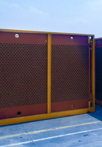
The roof superheater features rope holes strategically positioned for the inspection platform inside the furnace chamber and temporary inspection basket. These rope holes are located near the water-cooled walls of the front wall and two side walls. The superheater tubes in the ceiling consist of ϕ63.5 × 10mm and ϕ57 × 9mm tubes, both made of 15CrMoG material. Above the low-exit header box, 14 low-temperature superheater inlet header tubes extend from the Ⅰquadrant to the low-exit header box on top of the ceiling. The material used for the superheater tubes in the rear shaft package wall is 15CrMoG, comprising 43 ϕ31.8 × 6.5mm tubes in the horizontal flue side package wall, 891 ϕ38.1 × 6.5mm tubes in the front, middle, and rear package wall of the rear shaft, and 129 ϕ38.1 × 6.5mm tubes in the rear shaft side package wall.

2.2.2 Screen-Type Superheaters in the Upper Hearth Area:
The upper hearth area is equipped with screen-type superheaters, arranged in two rows along the depth of the hearth, with 19 screens in each row along the width of the hearth, making a total of 38 screens. The screens have an outer diameter of ϕ45mm, and the outer ring tubes are ϕ50.8mm. The transversal and longitudinal pitches of the screens are 1714.5mm and 57mm, respectively. The tubes of the internal heated surfaces in the hearth are made of two materials: Super 304H and HR3C. The outlet distribution box of each screen superheater is connected with the outlet collection box, where steam is mixed. The inlet section of the screen superheater has a transition section made of SA-213T22, and the outlet section has a transition section made of SA-213T92. Each tube screen has separate inlet and outlet distribution header boxes. The serpentine tubes of the screen superheater are supported by the header boxes and transferred to the large plate beams by the header box booms. The screen superheater inlet and outlet mixing box are divided into two sections and are site-welded.
2.2.3 High-Temperature Superheater:
The high-temperature superheater is composed of suspended tubes installed on the top of the flame folding angle, arranged in the width direction of the furnace. It consists of a total of 36 tube rows, with horizontal and longitudinal pitches of 914.4mm and 57mm, respectively. Each tube screen is made of 26 tubes, connected in parallel using Super 304H and HR3C materials. The inlet section of the high-temperature superheater is a transition section made of SA-213T91, while the outlet section is a transition section made of SA-213T92. Two adjacent pipe screens are introduced into the same high-temperature superheater inlet and outlet distribution manifolds, resulting in a total of 18 inlet and 18 outlet distribution manifolds.
The installation of these superheater components is vital for ensuring efficient steam generation and optimal performance of the boiler system.
Reheater System
The reheater system in the boiler comprises both cryogenic reheaters and high-temperature reheaters, each serving a crucial role in the steam generation process.
3.1 Horizontal Cryogenic Reheaters:
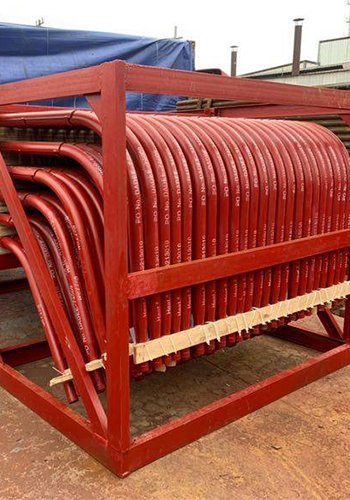
The horizontal cryogenic reheaters are positioned in the flue ahead of the rear shaft of the boiler, with a total of four groups. Each group is composed of six tubes wound with adequate spacing, resulting in a total of 297 rows arranged in the width direction of the furnace. The transverse pitch of these tubes is 114.5mm. In groups I and II of the cryogenic reheaters, two sizes of SA-21C tubes are used: ϕ57×4.5mm and ϕ57×5mm. In contrast, the first and second groups utilize ϕ57×4.5mm and ϕ57×5mm tubes made of 15CrMoG material, and the fourth group employs the same tube specifications but with the material 12Cr1MoVG.
3.2 Vertical Section of Low-Temperature Reheater:
The low-temperature reheater includes a vertical section with a horizontal pitch of 228.8mm. This section features 148 rows of horizontally arranged tubes. Two rows of horizontal section tubes combine to form one row of the vertical section. The tubes used in the vertical section have specifications of ϕ50.8 × 4.5mm and are made of SA-213T23 material.
3.3 High-Temperature Reheater:
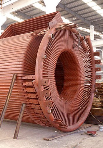
The high-temperature reheater consists of a total of 74 U-shaped tube screens. Each tube screen is composed of 12 tubes wound in parallel. These tube screens have a horizontal pitch of 457.3mm and a longitudinal pitch of 70mm. The tubes used for the internal heating surface of the furnace chamber are made of two materials: Super 304H and HR3C. The inlet section of the high-temperature reheater employs a transition section made of SA-213T22 material, while the outlet section utilizes a transition section made of SA-213T91 material.
The reheater system plays a critical role in raising the temperature of the steam to enhance the efficiency of the power generation process. The combination of cryogenic and high-temperature reheaters ensures optimal steam conditions for maximum power output.
In conclusion, the installation process of large-capacity and high-parameter units demands careful consideration in terms of selecting the appropriate lifting device, the sequence of heating surface installation, and the lifting points. In this paper, the case study of a 1000MW unit demonstrates the successful adoption of an intelligent winch lifting device for the boiler’s heating surface. Additionally, the thoughtfully arranged lifting sequence of the heating surface significantly reduces the complexity of the construction process.
By utilizing the intelligent winch with synchronized lifting capabilities, the project achieves greater efficiency and enhanced safety during the installation. This intelligent monitoring system, coupled with synchronized lifting, ensures the components are precisely placed and aligned, minimizing the need for multiple dismantling and assembly steps. As a result, the workload and construction costs are effectively reduced, streamlining the entire installation process.
The careful planning and implementation of the chosen lifting method and sequence play a crucial role in the successful installation of large-capacity and high-parameter units. The insights gained from this case study can serve as valuable guidance for similar projects in the future, enabling smoother and more efficient construction processes while meeting the stringent demands of such advanced power generation units.
[Source] HAN Song, ZHAN Changshan, HAO Yanqin, BOILER MANUFACTURING, CN23 – 1249 (2023) 03 – 0016 – 03