In recent years, the cost of power generation has been on the rise due to various factors, including fluctuations in coal prices and increased emphasis on environmental protection measures. Consequently, numerous power generation enterprises find themselves facing financial losses. To address these challenges and enhance the efficiency of coal utilization, power generation companies are actively seeking ways to improve their economic viability while simultaneously reducing coal consumption and curbing the emission of harmful pollutants such as CO2, NOX, and dust. In this pursuit, the implementation of low-temperature boiler economizers has emerged as a pivotal focal point for power generation enterprises.
The most significant loss in boiler operation is exhaust heat loss, which stands as the largest contributor to overall heat loss. This loss results from the heat carried away by the exhaust smoke as it is discharged into the atmosphere without being utilized. Primarily, the exhaust heat loss is influenced by the exhaust temperature and the volume of exhaust gas. There exists a crucial correlation between these factors, whereby every 15 ~ 20 ℃ rise in exhaust temperature leads to a 1% increase in exhaust heat loss (q2), consequently reducing boiler efficiency by 1% as well.
To mitigate the heat loss from exhaust smoke, enhance boiler efficiency, and optimize the entire unit’s economy, it is prudent to consider the integration of a low-temperature boiler economizer at the tail flue of the boiler. By doing so, the objective of reducing the exhaust smoke temperature can be achieved, leading to improved overall efficiency and cost-effectiveness of the system.
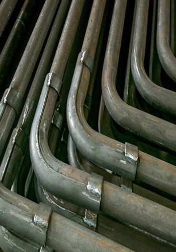
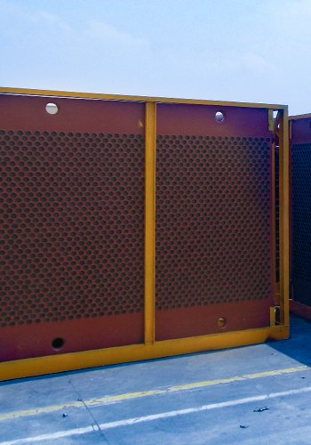
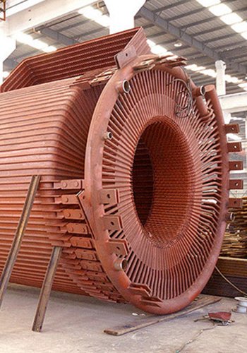
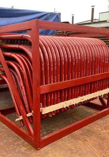
The low-temperature boiler economizer is a critical component for recovering and harnessing the heat present in the flue gas towards the end of the boiler operation. This economizer is primarily utilized to heat condensate, enabling it to absorb the waste heat from the exhaust smoke while simultaneously reducing the temperature of the exhaust gas. The preheated condensate is then directed back to the turbine condensate system, functioning akin to a low-pressure heater.
Furthermore, the incorporation of a low-temperature boiler economizer offers additional benefits. Firstly, it allows for the conservation of some turbine heat pumping, maintaining the turbine steam intake at a constant level. The saved pumping steam can then be employed to continue expanding and performing work within the turbine, leading to an enhancement in the overall unit’s economic efficiency.
Additionally, the economizer helps in saving a portion of the extracted steam that would otherwise be returned to the turbine. This saved extracted steam can be utilized to further expand and do work within the turbine, contributing to an overall improvement in the power plant’s economic viability. Consequently, the application of a low-temperature boiler economizer holds significant importance in conserving turbine energy consumption and elevating the overall economic efficiency of the entire power generation system.
Application of Low-Temperature Boiler Economizer
1.1 Domestic Application Scenario
In China, considerable efforts have been made in the installation and retrofitting of low-temperature boiler economizers in many power plants, supported by extensive research in this field.
For instance, a power plant in Shandong, equipped with two 100 MW coal-fired generating units, faced challenges arising from high coal sulfur content, boiler tail heating surface leakage, ash accumulation, and corrosion issues. These factors led to an exhaust temperature as high as 170 ℃. To address these concerns and enhance the overall operational efficiency of the unit, a low-temperature boiler economizer was introduced at the boiler tail, effectively reducing the boiler exhaust temperature.
Similarly, in a 300 MW thermal power plant located in Beijing, a low-temperature boiler economizer was employed to heat the heating return water. This approach not only decreased the unit’s steam extraction but also contributed to improved operation efficiency of the entire unit.
Moreover, during the third phase project of Shanghai Waigaoqiao Power Plant, two 1,000 MW units underwent retrofitting with low-temperature boiler economizers. These economizers were strategically positioned in the flue between the induced draft fan outlet and the desulfurization absorber tower inlet. The energy-saving benefits of this retrofit were clearly demonstrated through the performance test report.
1.2 Foreign Application
Internationally, the application of low-temperature boiler economizers has been prevalent for a longer period. In their efforts to reduce exhaust smoke temperature and minimize heat loss from exhaust gases, several foreign countries have undertaken various approaches:
- The Soviet Union incorporated low-temperature boiler economizers in the convection shaft flue’s lower part to heat the network water, achieving notable results in exhaust temperature reduction.
- A German power plant with two 800 MW lignite generating units introduced flue gas coolers between the electrostatic precipitator and the flue gas desulfurization absorption tower. The coolers effectively heated the boiler condensate.
- Another German lignite generating unit with a capacity of 1,000 MW implemented a separated flue system, significantly reducing the exhaust smoke temperature at the boiler’s end. Additionally, a low-temperature boiler economizer was installed in the bypass flue of the air preheater. Part of the flue gas was directed to the bypass flue, utilizing its heat to heat the boiler feed water.
- Tokyo Electric Power’s plant in Japan employed a water-mediated tubular flue gas – flue gas heat exchanger (GGH). The exothermic section of the GGH was situated upstream of the electrical dust collector, cooling the flue gas before it entered the low-temperature dust collector. The GGH’s flue gas heating section, positioned at the inlet of the chimney, utilized circulating water to heat the flue gas.
Overall, a comprehensive analysis of both domestic and foreign applications and retrofits of low-temperature boiler economizers reveals their significant role in reducing boiler exhaust temperature, conserving unit energy consumption, and enhancing the overall economic efficiency of power plants.
Precautions in the Arrangement and Selection of Low-Temperature Boiler Economizer
When considering the arrangement and selection of a low-temperature boiler economizer, several critical factors need to be taken into account to ensure optimal performance and durability. These precautions include:
2.1 Ash Accumulation Problem
Different types of heat exchanger tubes, such as light tubes, spiral ribbed tubes, and warped tubes, offer varying levels of heat transfer performance. Tubes with ribs and fins, like spiral ribbed tubes and warped tubes, exhibit better heat transfer efficiency and allow for a reduction in the number of rows of tubes and overall material consumption. Additionally, they lead to lower pressure drop throughout the system due to reduced resistance to flue gas flow.
However, the presence of ribs and fins on these tubes makes them susceptible to ash accumulation. To minimize the risk of ash buildup, careful consideration should be given to the flue gas flow rate and ash characteristics during the design process. Increasing the flue gas flow rate appropriately and arranging tube rows sensibly can help mitigate the ash accumulation phenomenon.
2.2 Wear Problem
In high-dust environments, such as areas with fly ash, the flue gas can cause abrasion to the tube walls. To address this, it is crucial to select wear-resistant materials for the heating surface during material selection. Moreover, the design should take into account the flue gas flow rate, as higher flow rates can exacerbate abrasion on the heating surface. Striking the right balance in the design can help reduce wear on the heating surface and consider the impact of flue gas flow rate on ash accumulation.
2.3 Acid Corrosion Problem
The presence of SO3 in the flue gas, when combined with water vapor, can generate sulfuric acid vapor. As the low-temperature wet flue gas flows through the equipment, water vapor condenses into liquid droplets, reacting with SO3 to form sulfuric acid liquid film, leading to acid corrosion on the equipment.
To mitigate acid corrosion, it is essential to consider the concentration of SO3 in the flue gas during actual operation. Employing a suitable SCR denitrification catalyst, optimizing combustion mode, and selecting appropriate coal can help minimize the impact of acid corrosion on the equipment.
2.4 Low Temperature Corrosion
Low-temperature corrosion occurs when the metal wall temperature of the boiler tail heating surface falls below the dew point temperature of the flue gas, resulting in the condensation of sulfuric acid vapor on the heating surface and subsequent corrosion. This corrosion can lead to the formation of acid-bonded ash, which strongly adheres to the surface and hinders ash removal during blowing.
To counter low-temperature corrosion, careful design of the smoke temperature and heat exchanger heat transfer temperature is essential to reduce the spread of corrosion and its adverse effects.
In conclusion, when arranging and selecting a low-temperature boiler economizer, it is vital to choose heat transfer and wear-resistant materials for the heat transfer surface, optimize the flue gas flow rate to reduce wear and ash accumulation, and consider the risks of acid and low-temperature corrosion. Reasonable layout and proper equipment selection can extend the service life of the low-temperature boiler economizer, reduce maintenance costs, and enhance the overall system efficiency.
Low-Temperature Boiler Economizer Arrangement Schemes and Characteristics
The installation of a low-temperature boiler economizer presents unique challenges due to the lower exhaust temperature, resulting in a smaller heat transfer temperature difference. As a consequence, the economizer requires a larger heat transfer area and occupies more space. Therefore, selecting an appropriate layout position during the retrofitting process is crucial to ensure the effectiveness of the low-temperature boiler economizer.
Depending on the equipment installed after the air pre-preheater in the boiler’s tail and the method of tail desulfurization, the following are the four main layout options for the low-temperature boiler economizer. The first three arrangements are suitable for wet desulfurization methods, while the fourth arrangement is designed for the semi-dry desulfurization method.
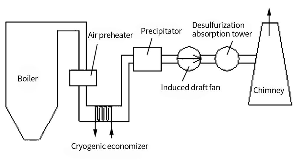
3.1 Flue Between the Outlet of the Air Preheater and the Inlet of the Dust Collector
(1) Connection Diagram of the Layout Scheme:
The low-temperature boiler economizer is positioned in the flue between the outlet of the air preheater and the inlet of the dust collector. The connection diagram is depicted in Figure 1.
(2) Characteristics of the Layout Program:
a) Advantages:
- Temperature Reduction: By passing the flue gas through the low-temperature boiler economizer before entering the dust collector, the flue gas temperature is effectively lowered. As a result, the volumetric flow rate of the flue gas decreases, leading to reduced space requirements for the dust collector and related materials.
- Power Reduction: The lowered flue gas flow rate not only reduces the size of downstream equipment, such as the dust collector, induced draft fan, and desulfurization absorption tower, but also leads to a decrease in power consumption throughout the entire power generation unit.
b) Disadvantages:
- Increased System Resistance: The installation of the low-temperature boiler economizer introduces additional resistance to the flue gas system, which may slightly impact the overall system efficiency.
- Low-Temperature Corrosion Risk: The cooled flue gas after passing through the low-temperature boiler economizer approaches the dew point temperature of the flue gas acid. This increases the risk of low-temperature corrosion for downstream equipment, including the dust collector, induced draft fan, and FGD absorber tower.
- Risk of Plugging and Wear: In cases where the boiler flue gas has not undergone dust removal, its high concentration of dust content poses a higher risk of plugging and wear for the low-temperature boiler economizer.
In conclusion, the layout scheme of placing the low-temperature boiler economizer between the outlet of the air preheater and the inlet of the dust collector offers several advantages, including temperature reduction and power savings. However, certain disadvantages, such as increased system resistance, the risk of low-temperature corrosion, and the potential for plugging and wear due to high dust concentration in the flue gas, must be carefully considered and mitigated during the design and operation of the system. Proper maintenance and material selection are essential to ensure the efficient and reliable performance of the low-temperature boiler economizer in this layout configuration.
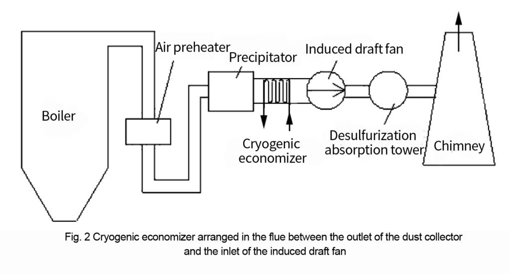
3.2 Flue Between Dust Collector Outlet and Induced Draft Fan Inlet
(1) Connection Diagram of the Layout Scheme:
The low-temperature boiler economizer is situated in the flue between the outlet of the dust collector and the inlet of the induced draft fan. The connection diagram is depicted in Figure 2.
(2) Characteristics of the Layout Program:
a) Advantages:
- Power Reduction: By positioning the low-temperature boiler economizer before the induced draft fan and other downstream equipment, the flue gas temperature is effectively lowered, resulting in reduced volumetric flow rate. As a consequence, the power consumption of the entire unit is decreased. This arrangement eliminates the risk of wear and clogging in the low-temperature boiler economizer.
- Reduced Equipment Corrosion: With the lowered flue gas temperature and the removal of alkaline particles by the dust collector, the risk of corrosion to downstream equipment is diminished.
b) Disadvantages:
- Increased System Resistance: The introduction of the low-temperature boiler economizer leads to additional resistance in the flue gas system.
- Risk of Low-Temperature Corrosion: The flue gas temperature at the tail end of the boiler significantly decreases after passing through the low-temperature boiler economizer, approaching the dew-point temperature of the flue gas. This raises concerns about the risk of low-temperature corrosion for the subsequent equipment, such as the induced draft fan and FGD absorber tower in the tail flue.
- Inefficiency in Dust Removal: The flue gas enters the low-temperature boiler economizer after dust removal by the dust collector. As a result, the economizer cannot be utilized to further decrease the flue gas temperature and flow rate, which would enhance the efficiency of dust removal.
In summary, the layout scheme involving the placement of the low-temperature boiler economizer between the dust collector outlet and the induced draft fan inlet offers notable advantages, such as power reduction and reduced equipment corrosion. However, certain drawbacks, including increased system resistance, the risk of low-temperature corrosion, and limitations in further enhancing dust removal efficiency, should be carefully considered and addressed during the design and operation of the system. Proper maintenance and material selection are crucial to ensure the successful integration and performance of the low-temperature boiler economizer in this layout configuration.
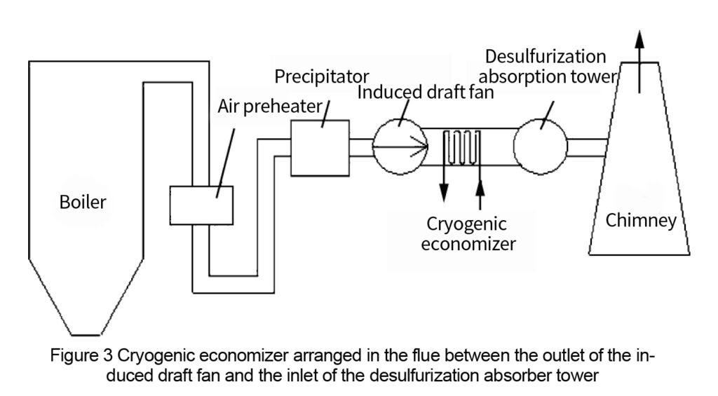
3.3 Flue Between Outlet of Induced Draft Fan and Inlet of Desulfurization Absorption Tower
(1) Layout Plan Connection Diagram:
The low-temperature boiler economizer is positioned in the flue between the outlet of the induced draft fan and the inlet of the desulfurization absorption tower. The connection diagram is depicted in Figure 3.
(2) Characteristics of the Layout Program:
a) Advantages:
- Improved Desulfurization Efficiency: The low-temperature boiler economizer serves to cool the flue gas in the tube-type Gas-Gas Heat Exchanger (GGH) heater. This cooling effect allows the flue gas entering the desulfurization absorption tower to achieve a lower temperature, meeting the optimal conditions for desulfurization.
- Reduced Risk of Abrasion and Clogging: As the flue gas undergoes dust removal treatment before entering the low-temperature boiler economizer, the dust content is significantly reduced. This, in turn, reduces the risk of fly ash abrasion and clogging on the surface of the low-temperature boiler economizer’s pipes.
- Decreased Equipment Corrosion: With fewer alkaline particles present in the flue gas entering subsequent equipment like the induced draft fan, low-temperature boiler economizer, and desulfurization absorption tower, the corrosion potential of these components is significantly reduced.
b) Disadvantages:
- Limitations in Dust Removal Efficiency: Since the flue gas enters the low-temperature boiler economizer only after undergoing dust removal by the dust collector, it cannot be utilized to further reduce the flue gas temperature and flow rate, which would enhance the dust removal efficiency of the dust collector.
- Long Condensate Pipeline: The low-temperature boiler economizer is situated far away from the main engine, resulting in longer condensate pipelines for heat exchange. This extended pipeline length increases resistance and power consumption in the system.
In summary, the layout scheme involving the placement of the low-temperature boiler economizer between the outlet of the induced draft fan and the inlet of the desulfurization absorption tower offers several advantages, including improved desulfurization efficiency, reduced risk of abrasion and clogging, and decreased equipment corrosion. However, limitations in enhancing dust removal efficiency and the challenge of overcoming larger resistance and power consumption due to the longer condensate pipeline should be carefully considered during the design and operation of the system. Proper design optimization and material selection are essential to maximize the benefits of the low-temperature boiler economizer in this layout configuration.
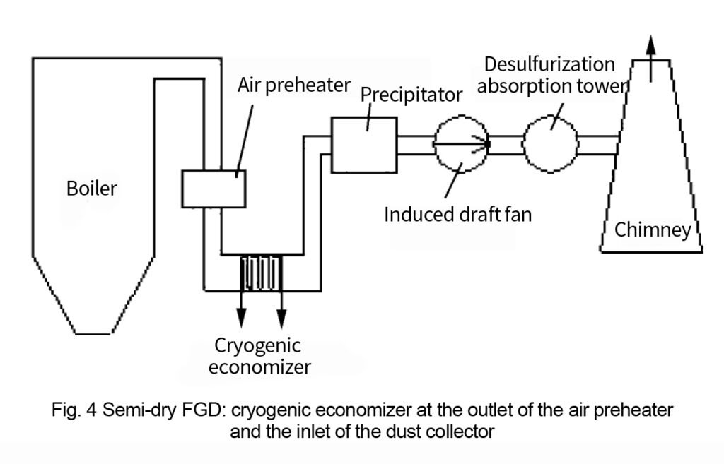
3.4 Layout Plan Under Semi-Dry Desulfurization Method
(1) Layout Scheme Connection Diagram:
When the flue gas desulfurization adopts the semi-dry desulfurization method, the arrangement scheme for the low-temperature boiler economizer is the same as the first arrangement scheme under the wet desulfurization method. This means that the low-temperature boiler economizer is placed in the flue between the outlet of the air preheater and the inlet of the dust collector. The connection diagram is shown in Figure 4.
(2) Characteristics of the Layout Program:
a) Advantages:
- Temperature Reduction: By passing through the low-temperature boiler economizer before entering the dust collector, the flue gas temperature is effectively lowered, resulting in a reduced volumetric flow rate of the flue gas. This leads to reduced area requirements for the dust collector, as well as decreased material consumption for dust collection. Moreover, the subsequent dust collector, induced draft fan, desulfurization absorption tower, and other equipment experience a corresponding reduction in flue gas volume flow, resulting in reduced power consumption for the entire power generation unit.
b) Disadvantages:
- Increased System Resistance: The introduction of the low-temperature boiler economizer increases the overall resistance in the flue gas system.
- Risk of Low-Temperature Corrosion: The flue gas temperature after passing through the low-temperature boiler economizer becomes close to the dew point temperature of the flue gas acid, creating a risk of low-temperature corrosion for subsequent equipment, such as the dust collector, induced draft fan, and FGD absorber tower.
- Risk of Clogging and Abrasion: If the boiler flue gas has not undergone dust removal, the high dust concentration poses a higher risk of clogging and abrasion for the low-temperature boiler economizer.
By comparing and analyzing the characteristics of different layout options for the low-temperature boiler economizer, it can be observed that when the boiler tail flue gas desulfurization adopts the wet desulfurization method, it is recommended to arrange the low-temperature boiler economizer in the flue between the outlet of the induced draft fan and the inlet of the FGD absorption tower. On the other hand, when the boiler tail flue gas desulfurization adopts the semi-dry desulfurization method, it is suggested to arrange the low-temperature boiler economizer in the flue between the exit of the boiler tail air preheater’s heating surface and the inlet of the dust collector.
In conclusion, selecting the appropriate layout of the low-temperature boiler economizer depends on the specific desulfurization method used and the design of the power plant. Careful consideration of the advantages and disadvantages of each layout scheme is essential to ensure the optimal performance and efficiency of the low-temperature boiler economizer in the power generation system. Proper maintenance and material selection are key factors in ensuring the long-term success of the chosen layout configuration.
Conclusion
a. The layout and selection process of the low-temperature boiler economizer requires careful consideration of factors such as ash accumulation, wear and tear, and appropriate flue gas flow rate. Special attention should be given to potential issues such as acid corrosion and low-temperature corrosion on the heat transfer surfaces and subsequent equipment. In this regard, proper selection of SCR denitrification catalysts, coal, combustion optimization, and reasonable heat exchanger design are vital in guiding the successful implementation of the low-temperature boiler economizer.
b. Placing the low-temperature boiler economizer in the tail flue of the boiler offers multiple advantages. It significantly reduces the flue gas temperature entering the desulfurization absorber tower, thereby improving desulfurization efficiency and reducing water consumption. Additionally, this arrangement allows for the recovery of a substantial amount of flue gas heat, resulting in reduced boiler flue gas temperature and improved overall economic performance of the power plant.
c. After comparing different arrangement schemes for the low-temperature boiler economizer, it is evident that for plants employing wet desulfurization, it is suitable to arrange the economizer in the flue between the outlet of the induced draft fan and the inlet of the desulfurization absorber tower. On the other hand, for those using semi-dry desulfurization, the optimal arrangement is to place the economizer in the flue between the outlet of the tail air preheater and the dust collector. This comparison provides valuable insights for selecting the appropriate layout of the low-temperature boiler economizer for waste heat utilization, depending on the specific desulfurization method employed.
In conclusion, the successful implementation of the low-temperature boiler economizer requires a comprehensive understanding of the heat transfer and corrosion factors, proper selection of materials and equipment, and careful consideration of the specific desulfurization method used. By optimizing the layout and selection of the low-temperature boiler economizer, power generation enterprises can enhance their overall efficiency, reduce environmental impacts, and achieve significant energy savings.
[Source] YANG Yuhuan, HOU Zhifu, Applied Energy Technology 2021 No.8:42-46
DHB Boiler
Discover The Superior Quality And Cutting-Edge Technology Of DHB Boilers. Explore Our Range Of Biomass Boilers, Waste Heat Boilers, And More. Take Your Industrial Operations To New Heights With DHB Boiler.
