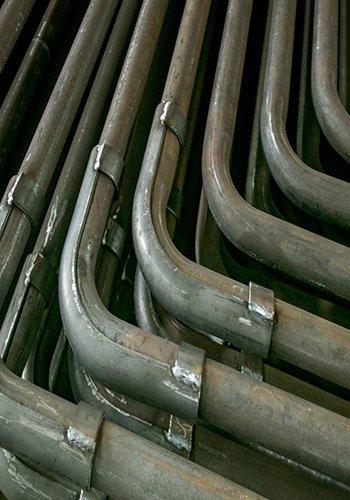
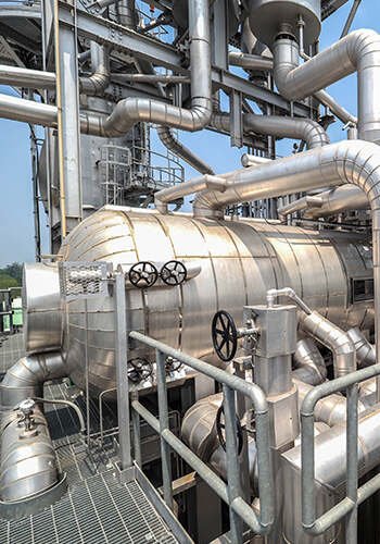
The high-temperature boiler economizer of the waste incineration power plant boiler in the circulating fluidized bed furnace is experiencing significant ash accumulation and severe coking. This has led to elevated exhaust gas temperatures. After approximately 25-30 days of operation, it becomes necessary to suspend furnace operations for treatment. Failure to address this issue promptly would adversely affect the long-term operation of the boiler. Please refer to Figure 1 for visual representation.

Based on the operational analysis, it has been determined that the primary cause of the issue is the high calorific value of the waste being fed into the furnace, coupled with a significant waste disposal volume. This combination results in excessively high flue gas temperatures at the furnace exit, leading to the relocation of ash accumulation from the superheater to the high-temperature economizer. As a result, the economizer’s ash cleaning device is unable to effectively remove the ash slag, potentially causing blockages in the air preheater and subsequent obstruction of the entire tail flue. This situation necessitates boiler shutdowns for maintenance, and in some cases, frequent replacement of the boiler economizer.
As part of the power plant’s preoperational measures, the decision was made to cease the operation of the high-pressure heater and lower the feedwater temperature from the designated 150°C to 103°C. The objective of this adjustment was to mitigate the flue gas temperature in the boiler economizer area by enhancing heat exchange within the boiler economizer. This step aimed to ensure the proper functioning of the air preheater and other associated equipment. However, these actions unintentionally led to the emergence of two issues: coking and low-temperature corrosion of the boiler economizer. Consequently, the economizer had to be replaced frequently to address these problems.
Ideas for Solutions
To address the mentioned issues, the proposed solution focuses on increasing flue gas heat exchange before the boiler economizer and relocating the coking area towards the empty flue or superheater area. This approach aims to facilitate ash removal and discharge through the ash hopper, alleviate coking and corrosion of the boiler economizer, prolong its lifespan, and reduce the frequency of boiler shutdowns and maintenance. The solution can be divided into five steps to extend the operating cycle:
1. Increased Heating Surfaces in High-Temperature Sections:
Consider adding a cyclone separator after the air flue with a vertical arrangement of water-cooled membrane wall partitions. This addition, estimated to be two or more, will lower the inlet flue temperature of the superheater and boiler economizer. By shifting the high-temperature zone of the flue gas forward to the air flue, coking and coking slag in the air flue can fall down and be removed by the slag remover without the risk of flue clogging. This modification can increase steam tonnage and potentially generate additional power if the boiler steam system and turbine design margins allow. Consequently, there will be no need to reduce the feedwater temperature and indirectly lower the flue gas temperature in the boiler economizer area by taking the high-pressure heaters out of service. The high-pressure heaters can be brought back into service, reducing pressure on the condenser and condensate pumps.
2. Addition of Hydraulic Ash Cleaning Device in the High-Temperature Section of the Air Flue:
Consider implementing hydraulic soot cleaning in the empty flue to control the inlet flue temperature of the superheater and boiler economizer. This allows for online soot cleaning without furnace shutdown. Before adopting this option, it is essential to verify if there is sufficient clearance of approximately 3m above the empty flue for the installation of the hydraulic ash cleaning device.
3. Modification of Secondary Air Pre-Heater:
The high secondary air temperature in the power plant, reaching 320°C, is primarily due to the use of an in-furnace tubular air preheater. The high flue temperature at the air preheater inlet leads to elevated secondary air outlet temperature, impacting the penetration and disturbance of the secondary air. If the secondary air temperature remains too high after implementing the measures in Sections 1.1 and 1.2, consider removing the uppermost stage of the bypass secondary air preheater to lower the secondary air temperature entering the furnace. Additionally, if the water temperature at the boiler economizer outlet is not excessively high, consider increasing the heating area of the boiler economizer to ensure the exhaust temperature remains within an acceptable range.
4. Conversion of Boiler Economizer and Air Preheater to Steam Soot Blowing:
Change the current pulse soot blowing system in the boiler economizer and air preheater to steam soot blowing. This modification enhances the effectiveness of soot cleaning.
5. Appropriate Increase in Feedwater Temperature:
Currently, the feedwater temperature is maintained at 103°C to reduce the smoke temperature. However, if the flue gas temperature decreases after implementing the technical improvements, increase the feedwater temperature to at least 130°C to prevent low-temperature corrosion of the boiler economizer.
By following these steps, the power plant can address the issues related to coking and corrosion, extend the operating cycle, and improve the overall performance and reliability of the boiler system.
Comparative Analysis of Retrofit Options
To reduce the inlet flue gas temperature of the high-temperature economizer, mitigate the risk of boiler economizer plugging, and improve the boiler operation cycle, four modification schemes are proposed. The main contents of the second scheme are as follows:

2.1 Addition of Boiling Boiler Economizer:
This modification involves removing the low-temperature superheater (8 rows of pipes) at the inlet of the third flue and replacing it with a high-temperature superheater (8 rows of pipes). Additionally, a serpentine tube-type boiling economizer (16 rows of pipes) is added below the high-temperature superheater in a downstream arrangement. The steam side from the fourth flue, above the high-temperature economizer, leads to the feed pipe into the lower collector box of the boiler economizer. The feed water is heated and partially vaporized as it passes through the boiler economizer. The steam and water mixture exits the upper collector box of the boiler economizer and is directed into the steam bag through a new water pipeline (as the existing steam bag lacks a reserved pipe connector, it must be sent from the original feed pipe connector into the steam bag). The boiling economizer pipes are made of 20G material, and a long retractable steam soot blower is used for ash cleaning.
The theoretical calculations for the new boiler economizer based on the boiling economizer design yield the following results: the new program’s heating surface area is approximately 140m2. This configuration can reduce the inlet flue gas temperature of the final stage of the high-temperature superheater by about 95°C and decrease the inlet flue gas temperature of the high-temperature economizer by approximately 43°C. As a result, the boiler’s exhaust gas temperature can be reduced by about 10°C.
The advantages of this scheme and the potential problems associated with it are summarized in Table 1.
| Advantages | Possible Issues |
| The new heating surface has a larger heat absorption capacity, resulting in higher efficiency. Significant reduction in flue gas temperature, resulting in improved overall performance. Compact structure and shorter remodeling period. | If the high-temperature economizer continues to experience feedwater vaporization after the modification, it may create hydrodynamic issues due to the height difference between the new boiling economizer and the high-temperature boiler economizer (10 meters). The new boiling economizer’s large heat absorption capacity may lead to localized superheated steam if the distribution of feedwater or vapor mixture is uneven. This could cause certain sections of the boiling economizer pipes to behave as superheater tubes, resulting in higher tube wall temperatures than the intended design. This poses a risk of pipe failure. The third flue’s inlet smoke temperature is approximately 800°C, which can damage the pipes when using steam soot blowing for cleaning. Additionally, the addition of 8 rows of pipes to the high-temperature superheater increases the total number of rows to 28, making soot cleaning more challenging. |
2.2 Addition of Diaphragm Water-Cooled Walls to the Air Flue
In this modification, two water-cooled membrane wall partition walls are added to the second air flue after the cyclone separator. Each partition wall has a heat area consistent with the second flue side of the boiler. Water supply pipes are introduced from the boiler downtube, and the upturn pipe utilizes the existing membrane wall upturn pipe. A new diaphragm wall upturn pipe is added, connecting to the existing upturn pipe joint and leading into the steam packet.

The theoretical calculations for the new two water-cooled membrane wall partition walls yield the following results: the program’s new heating surface area is approximately 92m2 (when calculating the heat-absorbing area on both sides, the total is 184m2). This configuration can reduce the inlet flue gas temperature of the low-temperature superheater by about 78°C, decrease the inlet flue gas temperature of the final stage of the high-temperature superheater by approximately 70°C, and lower the inlet flue gas temperature of the high-temperature boiler economizer by around 33°C. Consequently, the boiler’s flue gas temperature can be reduced by about 8°C.
The advantages of this scheme and the possible problems are summarized in Table 2.
| Advantages | Possible Issues |
| The new heating surface has a larger heat absorption capacity, resulting in higher efficiency. Significant reduction in flue gas temperature, leading to improved overall performance. Potential for enhanced effectiveness of hydraulic ash cleaning if implemented in the future. Expected increase in total evaporation, resulting in additional power generation revenue. Reduction in flue gas flow rate in the third flue superheater convection tube bundle, decreasing wear on the flue gas and prolonging the superheater’s lifespan. | Modification of the existing membrane wall rising pipe due to the absence of a reserved pipe joint in the steam bag. This requires more complex design and construction. Impact on the existing water circulation system due to the introduction of the diaphragm wall rising pipe. Comprehensive water circulation calculations for the entire furnace are necessary to assess and determine the potential impact. If the heating surface of the superheater is not increased, there may be a reduction in heat absorption. It is crucial to calculate whether the desired main steam temperature can still be achieved. Longer duration and higher cost associated with the modification process. |
2.3 Increase the Area of Low-Temperature Superheater
In this modification, the existing cryogenic superheater at the third flue inlet, which currently has 8 rows of pipes, can be increased to 20 rows of pipes while keeping the steam side connection unchanged. Additionally, a new level of water spray cooling device needs to be added to prevent the superheater from overheating.
The thermal calculation results for the new low-temperature superheater program are as follows: the program’s new heating surface area is approximately 127 m2. The inlet flue temperature of the low-temperature superheater remains unchanged, but the inlet flue temperature of the final high-temperature superheater can be reduced by about 51°C. Similarly, the inlet flue temperature of the high-temperature economizer can be lowered by approximately 23°C, resulting in a reduction of about 4°C in the exhaust smoke temperature from the boiler.
The advantages of this scheme and the possible problems are summarized in Table 3.
| Advantages | Possible Issues |
| Ease of retrofitting and shorter construction period compared to other schemes. Reliable retrofit program with low risk, providing predictable and controllable expected results. Lower cost associated with the retrofitting process. | The retrofitting of the low-temperature superheater does not result in a reduction in the inlet flue gas temperature. As the inlet flue gas temperature remains close to 800°C, there is a risk of ash plugging in this section. The degree of reduction in flue gas temperature is limited. Although the inlet flue gas temperature of the high-temperature economizer can be reduced, it still remains relatively high. There is a need to increase the level of water spray to further reduce the temperature, requiring corresponding changes to the soft control system. Please refer to Table 3 for a summary of the advantages and possible issues related to this scheme. |
2.4 Increase Convective Tube Bundle + Superheater + Slag Tube
In this modification, the castables above 1.5m of the temperature measurement point in the upper part of the second combustion chamber of the furnace are removed. The convection tube bundle, superheater, and part of the slag condensate pipe are increased based on operational data. The objective is to control the flue gas inlet temperature of the upper part of the high-temperature boiler economizer at around 450°C.
It is important to note that by removing the castables in the upper part of the temperature measurement point in the second combustion chamber, the exposed water-cooled wall pipelines may be at risk of high-temperature corrosion. Therefore, it is necessary to enhance monitoring and maintenance during operation after the technical modification.
Please ensure that proper monitoring and maintenance procedures are in place to address any potential corrosion issues and maintain the performance and integrity of the modified components.
Solving Ash Accumulation and Coking Issues in Waste Incineration Power Plant Boiler Economizer Conclusions
Based on the comparative analysis, it can be concluded that the program to increase the boiling economizer, although optimal in theoretical calculations, poses greater risks and lacks controllability in actual operation. Therefore, it is not recommended to implement this program.
On the other hand, the programs to increase the diaphragm wall membrane wall and increase the area of the low-temperature superheater are more conservative options. These modifications result in a relatively small reduction in flue gas temperature.
The program involving knocking out the castable material in the upper portion of the temperature measurement point in the second combustion chamber and increasing the convective tube bundles, superheater, and part of the slag tube requires further analysis and accounting. It is suggested to implement this program gradually, starting with a technical reform on one furnace, and then optimize the technical reform based on the actual operating results. This approach ensures system stability and long-cycle operation.
In conclusion, careful consideration should be given to the risks, controllability, and effectiveness of each modification program, and a step-by-step approach should be taken to ensure the stability and success of the technical reforms.
[Source] Wu zhanheng, Technology Innovation and Application 2021-28:143-145