The largest source of heat loss in boilers is associated with boiler exhaust. In the case of large and medium-sized boilers operating under normal conditions, exhaust loss typically represents 4% to 8% of the fuel heat input of the boiler. In active coal-fired thermal power units in China, the design temperature for coal-fired boiler exhaust is generally set at around 120℃ to 140℃. However, during actual operation, the exhaust temperature typically ranges from 125℃ to 150℃, and for lignite boilers, it can reach approximately 170℃. This high exhaust temperature is a common occurrence that leads to significant energy wastage.
The elevated temperature of the exhaust smoke contributes to increased specific resistance of dust, resulting in a larger volume and faster flow rate of flue gas. Consequently, this decrease in dust removal efficiency poses a challenge.
In the current context of emphasizing energy conservation and emission reduction, the utilization of low-temperature Boiler Economizer has proven to be effective in reducing boiler exhaust temperatures by approximately 30℃ to 40℃. This implementation has yielded positive outcomes. By reducing the exhaust temperature by 15℃ to 25℃, it is possible to enhance the unit’s efficiency by approximately 1%.
Although the installation of a low-temperature Boiler Economizer leads to an increase in flue gas resistance, the associated power consumption resulting from this resistance accounts for less than 10% to 30% of the cost savings. Consequently, the installation of a low-temperature Boiler Economizer not only achieves energy savings but also reduces production costs, thereby holding significant practical significance.
Application Solutions
1.1 Unit Overview
The power plant consists of two 330 MW coal-fired units equipped with SG-1036/17.5-M871 subcritical boilers. These boilers employ a primary intermediate reheat, control cycle steam turbine furnace. They feature a single hearth, Π-type structure with balanced ventilation, four-corner cut-circle combustion, oscillating burner temperature control, solid slag discharge, and an all-steel frame suspended structure arranged in an open-air configuration.
The unit is equipped with a three-bin Junker-type air preheater, medium-speed coal mills, a direct blowing positive pressure cold primary air powder making system, and a double chamber four electric field electric dust collector.
Currently, the exhaust temperature of the unit stands at 140℃. To enhance the unit’s economy, ensure the safe and stable operation of the electric precipitator, and achieve a dust outlet concentration of ≤20 mg/m3 (which should be further reduced whenever possible), a retrofit project involving the installation of a low-temperature Boiler Economizer is being undertaken. This retrofit aims to capture the waste heat from the flue gas, reduce the exhaust temperature, and optimize the overall performance of the unit.
1.2 Process Flow
The new low-temperature Boiler Economizer is designed to operate under specific conditions. The inlet flue gas temperature is 140℃, and it is reduced to 90℃ after passing through the economizer. The low-temperature Boiler Economizer functions as a countercurrent heat exchanger for both the flue gas and condensate. It is installed in the four horizontal flues located ahead of the electrostatic precipitator.
Based on the unit’s heat balance diagram, the retrofit proposal involves diverting a portion of the condensate from the 8th low-pressure heater inlet and 7th low-pressure heater outlet condensate system. This diverted condensate, mixed with other condensate, is introduced into the low-temperature Boiler Economizer at a temperature of 65℃. Within the economizer, the temperature of the condensate rises to approximately 100℃ before being returned to the 6th low-pressure heater inlet. The inlet temperature is regulated using a control valve in accordance with the unit load and seasonal conditions. Additionally, a condensate recirculation pipe is installed to facilitate the counter-current heat transfer between the flue gas and condensate within the low-temperature Boiler Economizer. This pipe allows for adjustments to the inlet water temperature of the economizer.
The low-temperature Boiler Economizer is designed to accommodate the full capacity of the condensate. The process flow is illustrated in Figure 1, and the key technical parameters are provided in Table 1.

| Total flue gas flow rate/(m3 · h-1) | 1229355 |
| Total heat exchange area/m2 | 23390 |
| Total heat exchange/(kJ · s-1) | 22980 |
| Inlet flue gas temperature/℃ | 140 |
| Outlet flue gas temperature/℃ | 90 |
| Pressure loss on the flue gas side/Pa | 500 |
| Inlet water temperature/℃ | 65 |
| Outlet water temperature/℃ | 100 |
| Inlet flow rate/(t · h-1) | 580 |
| Water side pressure loss/MPa | 0.33 |
| Flue gas flow rate/(m · s-1) | 9.5 |
1.3 Determination of Inlet Water Temperature
Currently, there are several methods available for calculating the boiler acid dew point temperature. Among these methods, the calculation standard proposed by the former Soviet Union in 1973 has been widely used due to its close alignment with actual values. This method is based on practical observations and has proven to be more accurate. The calculation formula is shown in Equation (1).

tld is the dew point of pure water vapor
Sx is the fuel-converted sulfur
Ax is the fuel-converted ash
αh is the share of fly ash
β is the coefficient related to the excess air coefficient at the outlet of the furnace.
Based on the analysis of the boiler coal quality data, the water dew point temperature was determined to be 39°C, while the acid dew point temperature was calculated to be 97°C. It is important to note that the maximum rate of low-temperature dew-point corrosion in the flue gas occurs when the flue gas dew-point temperature is below 10℃ to 30℃, and the water dew-point temperature is below that range.
To prevent severe corrosion of the heat exchanger tubes, it is necessary to ensure that the tube wall temperature remains above these critical corrosion zones. Therefore, taking into account the corrosion rate of the heat exchanger tubes made of ND steel at different wall temperatures, it has been determined that the inlet temperature of the condensate entering the low-temperature Boiler Economizer should be maintained at 65℃.
To achieve this, a mixture of condensate from the 8th low-pressure heater inlet and 7th low-pressure heater outlet is directed to the low-temperature Boiler Economizer, where it is blended to achieve a temperature of 65℃.
1.4 Anti-wear, Anti-corrosion, and Anti-dust Accumulation Measures
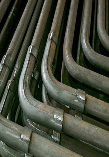
In the low-temperature Boiler Economizer, ND steel is chosen as the material for the heat exchanger pipes. ND steel, composed of 09CrCuSb, is currently considered the ideal steel for “sulfuric acid low-temperature dew-point corrosion” both domestically and internationally. It exhibits a corrosion resistance 2.97 times higher than stainless steel and 14.11 times higher than carbon steel.
To address the prevalent issues of wear, leakage, local corrosion, and ash accumulation in the heat exchanger tube bundle of the low-temperature Boiler Economizer, several measures have been implemented. In terms of structural design, the flue gas flow rate is controlled to be between 9 m/s and 10 m/s. This ensures a self-cleaning flow rate for the flue gas while effectively controlling wear on the surface of the heat exchanger elements. Deflector plates are installed in the flue, and computational fluid dynamics (CFD) simulations are used to prevent local areas with increased fly ash concentration and uneven flow.
The low-temperature Boiler Economizer is positioned ahead of the dust collector, where the flue gas contains a high concentration of soot. To combat severe abrasion of the heat exchanger tubes in the inlet section caused by the flue gas, anti-abrasion tubes are arranged on the windward side of the first row of tubes. In the past, corrosion leakage was observed in the welds of heat exchanger pipes and elbows due to the scouring effect of the flue gas. To mitigate this, the elbow welds are positioned outside the flue, thereby avoiding corrosion caused by the flue gas and preventing water-side leakage.
To ensure effective sootblowing, an acoustic sootblower is installed in the high-temperature section of the low-temperature Boiler Economizer, while a steam sootblower is employed in the low-temperature section. This combination enables efficient sootblowing to keep the heat exchanger surfaces clean. Intermittent blowing of the heat exchanger surface is performed during normal equipment operation to prevent ash accumulation.

1.5 Operation Strategy
During boiler operation, fuel characteristics and working conditions may change, including situations with low load. It is essential to maintain the flue gas temperature at the outlet of the low-temperature Boiler Economizer within the range of 90℃±1℃ to ensure the efficiency of the downstream dust collector.
If the outlet flue gas temperature of the low-temperature Boiler Economizer falls below 90℃, the following strategies can be implemented:
- Reduce the amount of condensate directed to the inlet of the 8th low-pressure heater and increase the amount of condensate directed to the outlet of the 7th low-pressure heater. This adjustment increases the inlet temperature of the heat exchanger, aiming to elevate the flue gas temperature at the heat exchanger outlet. This helps to prevent severe low-temperature corrosion in the heat exchanger tubes.
- Decrease the total flow rate into the heat exchanger. This reduction in flow rate raises the flue gas temperature at the heat exchanger outlet, serving the same purpose of preventing excessive low-temperature corrosion.
Conversely, if the outlet flue gas temperature of the low-temperature Boiler Economizer exceeds the desired range, the following adjustments can be made:
- Increase the amount of condensate directed to the outlet of the 8th low-pressure heater and decrease the amount of condensate directed to the outlet of the 7th low-pressure heater. This modification reduces the heat exchanger inlet water temperature, thereby facilitating a decrease in flue gas temperature and maximizing waste heat recovery.
By implementing these operation strategies, it is possible to regulate the flue gas temperature at the outlet of the low-temperature Boiler Economizer, ensuring efficient operation of the dust collector and optimizing waste heat recovery.
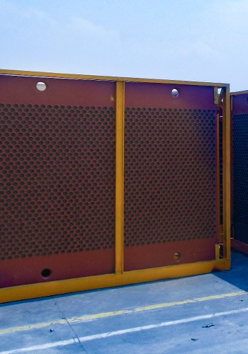
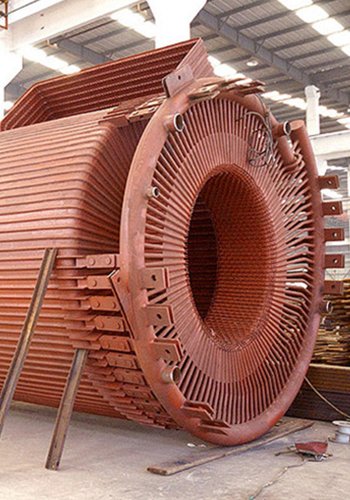
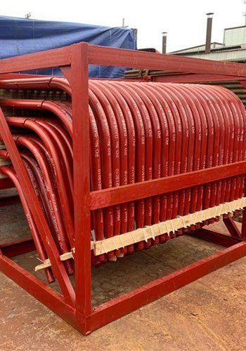
The low-temperature Boiler Economizer is designed with a modular approach, employing a grouping design. It is divided into three sections in the direction of airflow and two layers in height. Manual isolation valves are installed between each module and the main water supply pipeline, allowing for convenient commissioning of the entire system or specific groups based on the operating conditions of the boiler.
During low-load conditions, the opening and closing of isolation valves in the high-temperature and low-temperature sections of each low-temperature Boiler Economizer can be adjusted. By shutting off the high-temperature section, the low-temperature section of the Boiler Economizer remains in operation. This enables the control of the flue gas temperature at the outlet of the low-temperature Boiler Economizer, maintaining it within the target range of 90℃±1℃.
In the event of leakage in a module of the low-temperature Boiler Economizer, the manual isolation valve between the front and rear header boxes of the affected module and the main water supply pipeline is closed. This action isolates the module from operation, and necessary repairs can be carried out during favorable conditions.
The schematic layout of the low-temperature Boiler Economizer heat exchanger module is depicted in Figure 2, while the water-side heat exchanger circuit is illustrated in Figure 3.

2. Economic Analysis
The addition of a low-temperature Boiler Economizer may not directly improve boiler combustion or other operational conditions, nor does it enhance the efficiency of the boiler itself. However, from the perspective of the entire power plant, it contributes to overall efficiency improvement.
The low-temperature Boiler Economizer recovers waste heat from the flue gas at the boiler’s end. This recovered heat is utilized to heat the condensate entering the low-pressure heater in the turbine. Furthermore, the extraction steam from the turbine and all levels of exhaust extraction steam are returned to the turbine to continue performing work. This effectively increases the work output of the low-pressure cylinder.
Simultaneously, the increased work output of the low-pressure cylinder leads to an increase in theoretical exhaust from the low-pressure cylinder. Consequently, the increased heat load on the condenser causes an increase in condenser pressure and specific enthalpy of the low-pressure cylinder exhaust. As a result, the work done by the low-pressure cylinder decreases. However, the increase in work done by the gas pressure cylinder is significantly greater than the decrease in work done by the low-pressure cylinder. This ultimately reduces the overall heat consumption of the unit.
Therefore, while the low-temperature Boiler Economizer may not directly improve the efficiency of the boiler itself, it plays a vital role in recovering waste heat, optimizing the power plant’s efficiency, and reducing heat consumption.
Indeed, the increase in work done by the gas pressure cylinder is typically larger than the decrease in work done by the low-pressure cylinder when utilizing a low-temperature Boiler Economizer. This results in reduced heat consumption of the unit and improved overall plant efficiency.
By harnessing the waste heat from the boiler exhaust and implementing a low-temperature Boiler Economizer to heat the condensate, it is possible to heat 580 t/h of condensate from 70℃ to 100℃. This, in turn, reduces steam turbine pumping and lowers the coal consumption for power generation by approximately 2.87 g/kWh.
The installation of a low-temperature Boiler Economizer also contributes to the reduction of flue gas temperature from 140℃ to 90℃. This decrease in temperature leads to a reduction in the specific resistance of dust, resulting in reduced power consumption by the dust collector. Additionally, the lower flue gas temperature significantly decreases the volume of desulfurization cooling water required, thereby reducing both water consumption and power consumption for desulfurization. Moreover, the reduced volume flow of cooled flue gas leads to energy savings for the induced draft fan.
In summary, the utilization of a low-temperature Boiler Economizer provides multiple benefits, including reduced coal consumption, improved dust collection efficiency, reduced water and power consumption for desulfurization, and energy savings for the induced draft fan. These factors contribute to overall energy efficiency and cost reduction in the power plant.
3 Conclusion
In conclusion, the retrofit of a 2×330MW coal-fired unit in a power plant with an additional low-temperature Boiler Economizer has yielded significant benefits. The installation of the economizer has effectively lowered the flue gas temperature from 140℃ to 90℃, allowing for the recovery of 22,980 kW of waste heat. Furthermore, the dust concentration at the outlet of the dust collector has been reduced to ≤20 mg/m3, indicating improved air quality and compliance with environmental regulations.
The introduction of the low-temperature Boiler Economizer has resulted in reduced coal consumption for power generation and improved unit efficiency. Notably, the economizer has demonstrated minimal corrosion, wear, bias flow, or ash accumulation after operation, ensuring its reliable performance.
Overall, the implementation of the low-temperature Boiler Economizer has proven to be an effective energy-saving measure, enabling thermal power enterprises to achieve clean and efficient development. The economic benefits and application value of this technology transformation are significant, further validating its positive impact on power plant operations.
[Source] Wen Baohui, Design and Application of Low Temperature Boiler Economizer for 330MW Coal-fired Unit, SHANXI CHEMICAL INDUSTRY Total 198 No.2,2022

Don’t miss out on the game-changing benefits of low temperature boiler economizers. Discover how to boost efficiency and reduce costs in 330MW coal-fired units.