Boiler combustion in thermal power generation units is quite the enigma. It’s a complex process, and figuring out how well the boiler is doing isn’t as straightforward as you might think. In fact, it’s where most boiler problems tend to crop up. As we grapple with the growing scarcity of fuel, many thermal power generation companies are turning to coal blending to cut costs. While this might seem like a good idea, it’s actually making the control of boiler combustion much more intricate and causing a spike in the rate of boiler failures.
One common issue we face during boiler operation is something known as “combustion bias burn.” This phenomenon leads to temperature imbalances along the boiler’s water walls, causing temperature fluctuations, which are a dime a dozen. However, these temperature swings come with serious consequences. Prolonged uneven burning in the boiler can lead to a host of problems, including localized coking inside the furnace, tubes overheating and bursting, and high-temperature corrosion. These issues pose a significant threat to both the safety and economic performance of the unit.
Currently, the most widely used method for adjusting boiler water wall temperatures involves tinkering with the combustion on the boiler’s fire side. This includes adjustments like fine-tuning the primary air, secondary air, coal-water ratio, and burner settings, all in an attempt to control and regulate wall temperature. The problem here lies in the sheer number of measurement points along these water walls. It’s a real challenge for operators to keep a real-time watch on all these points, making effective wall temperature control quite the uphill battle. As it stands, the existing wall temperature control methods don’t offer a reliable closed-loop control solution.
So, what’s the solution to this conundrum? Well, we aim to convert boiler water wall temperature data into something more manageable: wall temperature coordinate data. By doing this, we can adjust the distribution of secondary air in the combustion zone, effectively repositioning the center of the furnace flame coordinates. This clever adjustment creates a system where we can control the center of the boiler water wall temperature by manipulating the center of the furnace flame. It’s a game-changer for boiler efficiency and safety, and it’s what we’re all about here.
Control Program
1.1 Our Comprehensive Control Strategy
Let’s dive into the nuts and bolts of our control program. We’ve got this fantastic piece of tech called the Boiler Acoustic Temperature Measurement device. It operates on a simple principle: it measures how fast sound travels at various temperatures. But what’s it do? Well, it keeps a watchful eye on the combustion temperature field within the furnace flame of our boiler. We install this acoustic temperature measurement device just below the angle where the flame folds, roughly one meter away from the action. The data it collects provides insights into how well the pulverized coal is burning in the embers area of the boiler.
Now, when it comes to monitoring the temperature of our boiler’s walls, we’ve got a straightforward approach. We tap into the wall temperature data directly from the Distributed Control System (DCS) of our power plant. With this data in hand, we embark on a journey of computational integration, merging two sets of data: the temperature field and the wall temperature. This integration helps us create a model that identifies what’s going on. So, what do we do with this newfound knowledge?
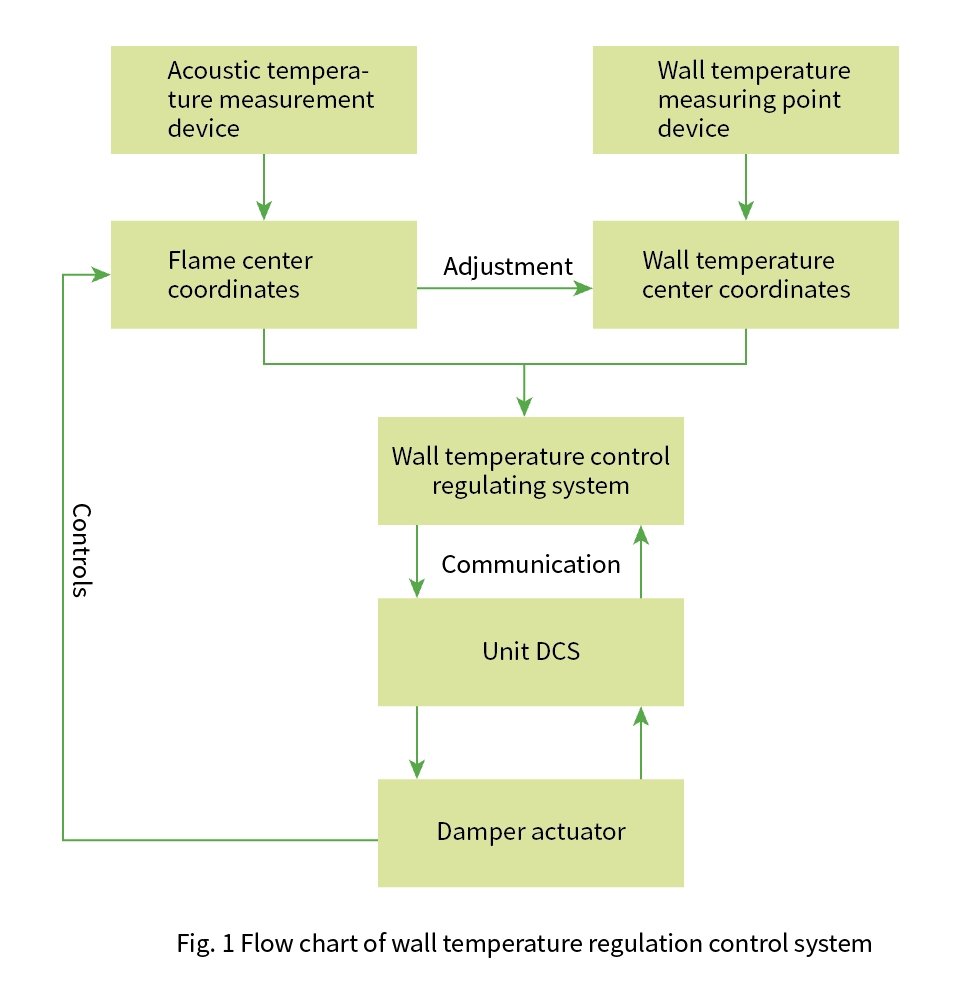
We use it to regulate the secondary damper in the embers area. Think of it as the control center. By adjusting the secondary damper’s position, we’re effectively managing the flame’s center. And guess what? This has a direct impact on wall temperature regulation. It’s all about keeping things in balance. If you want to see how it all comes together, take a peek at Figure 1 – it illustrates our control program flow.
1.2 Calculating the Center of the Temperature Field
Now, let’s get into the nitty-gritty of how we calculate the center of our boiler’s combustion temperature field. This field has two key characteristics: width and depth. Our trusty online monitoring module measures the average temperature within these parameters and helps us spot trends, especially when there’s uneven burning going on. Here’s how we go about it:
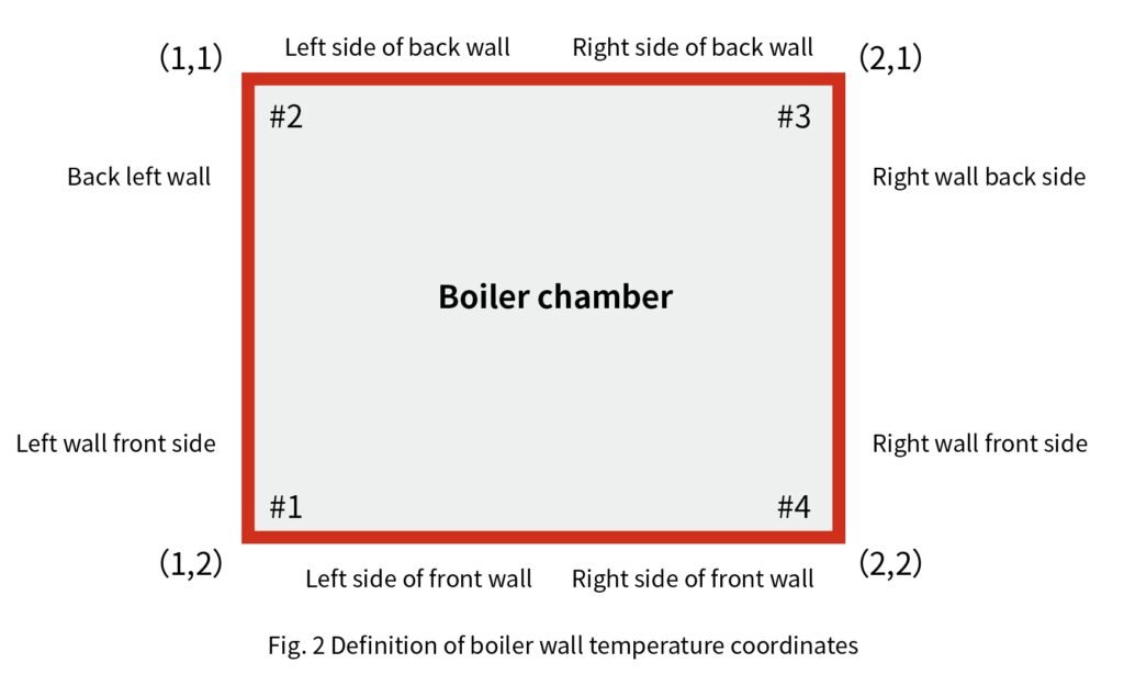
Step 1: We start by setting up a coordinate system right within the furnace. We pinpoint the origin at the corner vertex of section #2 – that’s our (0, 0) point. The X-axis represents the width of the furnace, and the Y-axis corresponds to the depth of the furnace. We’ve got a pretty simple convention going on here: positive values extend to the right along the X-axis, and downward coordinates are considered negative.
Step 2: Now, let’s talk algorithms. We’ve got a specific one in place to work this all out. It goes a little something like this:Where:
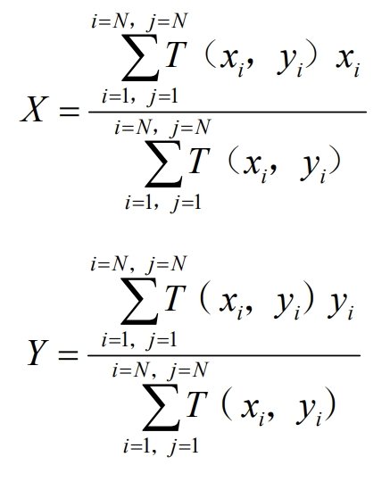
Where:
- X, Y represent the calculated center coordinates of the temperature field within the furnace cross-section.
- (x, y) refers to each temperature block’s center point, as measured by our online combustion temperature field monitoring module.
- T(x, y) denotes the temperature value at the center of each of these temperature blocks, also measured by our trusty online monitoring module.
So, you see, it’s all about crunching numbers to pinpoint where the heart of our temperature field lies. This helps us keep things in check and ensure our boiler operates smoothly.
1.3 Transforming Wall Temperature Data into Wall Temperature Coordinates
Now, let’s get into the specifics of how we transform wall temperature data into a more manageable format, what we call “wall temperature coordinates.” Our primary focus here is optimizing the temperature adjustments for the water walls in our vertical pipe boiler.
Step 1: We start by using specialized boiler water wall temperature measurement equipment. This equipment helps us gather temperature data from the front wall, left wall, rear wall, and right wall of our boiler. Each of these walls has a total of 32 measurement points.
Step 2: To make this data more manageable, we divide these 32 measurement points into two groups of 16 each. In other words, we split each wall into two parts, such as the left side and the right side of the front wall, the front and back of the left wall, the left side and the back of the rear wall, and the front and back of the right wall.
Step 3: For each of these 16 points, we calculate the average wall temperature. This average becomes a representative temperature for a specific side of each wall.
Step 4: Now, things get a bit interesting. We take these average wall temperature data combinations and use them to create what we call “corner wall temperature data temperature coordinates.” Here’s how it works:
- The combination of wall temperature data from the left side of the front wall and the front side of the left wall forms the #1 corner wall temperature data temperature coordinate, which we’ll call t1.
- The combination of wall temperature data from the back side of the left wall and the left side of the back wall forms the #2 corner wall temperature data temperature coordinate, known as t2.
- Similarly, the combination of wall temperature data from the right side of the back wall and the back side of the right wall forms the #3 corner wall temperature data temperature coordinate, or t3.
- Finally, the combination of wall temperature data from the front side of the right wall and the right side of the front wall creates the #4 corner wall temperature data temperature coordinate, labeled as t4.
We visually represent these wall temperature coordinates of the furnace in a diagram, which you can see in Figure 2. This transformation helps us better understand and manage the wall temperatures within the boiler, contributing to smoother and more efficient operation.
Defining Corner Coordinates and Transforming Wall Temperature Data
Alright, let’s delve into how we define corner coordinates and transform our wall temperature data into something more meaningful.
Step 1: We’ve defined four fixed corner coordinates for our boiler:
- Corner #1: (x1, y1) = (1, 2)
- Corner #2: (x2, y2) = (1, 1)
- Corner #3: (x3, y3) = (2, 1)
- Corner #4: (x4, y4) = (2, 2)
These coordinates help us establish specific points within the boiler’s layout.
Step 2: Next, we group two sets of wall temperature data that are closest to each corner of the boiler. This means we’re taking measurements from adjacent sides of each corner. The integration formula we use for this process is as follows:
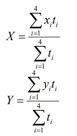
Where:
- X represents the converted wall temperature horizontal coordinates.
- Y represents the converted wall temperature vertical coordinates.
- t represents the wall temperature data integrated from both sides of the adjacent corner.
Step 3: After applying this integration formula, we’re left with wall temperature coordinate data in the format (X, Y). These coordinates provide us with insights into how the wall temperatures fluctuate across the boiler. In essence, they help us understand and manage the variations in wall temperatures effectively.
This transformation is a key part of ensuring our boiler operates smoothly and efficiently.
Wall Temperature Adjustment Control System
In this section, we’ll dive into the details of our wall temperature adjustment control system. Our focus here is to maintain precise control over the boiler’s wall temperature, ensuring optimal operation. Let’s break it down.
The Control Strategy: Our control scheme revolves around regulating the center position of the furnace flame. We do this by manipulating the combustion wind angle operation through command control. By influencing the center position of the furnace flame, we can, in turn, impact the wall temperature’s center, effectively achieving our goal of wall temperature regulation.
Advanced Predictive Control: To accomplish this, our wall temperature adjustment control system employs an advanced predictive control strategy. It leverages data from two sources: the temperature field flame center coordinate data, obtained from our acoustic temperature measurement equipment, and wall temperature data from the Distributed Control System (DCS). These data streams are converted into wall temperature coordinates and communicated to an industrial control machine using the Modbus communication protocol.
Model Identification: Our control system is smart and dynamic. It processes embers damper angle operation data, temperature field data, and wall temperature data to identify two crucial models. The first model helps us understand the embers damper angle operation and the temperature field flame center. The second model provides insights into the temperature field flame center coordinates and wall temperature center coordinates.
Closed-Loop Control: Armed with these models, we establish a closed-loop control system. The embers damper angle operation is used to control the flame center coordinate, and, in turn, this impacts the wall temperature coordinates. This closed-loop control ensures that wall temperature remains within desired parameters.
Automation at Its Best: Our wall temperature adjustment control system is incredibly efficient. It eliminates the need for manual adjustments by operators. Instead, it automatically manages wall temperature adjustments. However, in cases of abnormal wall temperature, operators can still step in and make macroscopic adjustments as needed.
In a nutshell, our control system is all about precision and automation. It keeps our boiler running at optimal conditions while ensuring the safety and efficiency of the wall temperature adjustments.
Wall Temperature Regulation Control Effect
In this section, we’ll delve into the outcomes of our wall temperature regulation control system, particularly concerning the HG-1125/25.4-HM2 type 350 MW supercritical wall cut-circle boiler produced by Ha Boiler Factory. Here’s a rundown of the effects observed:
High-Temperature Corrosion Challenge: The boiler’s water wall, especially around the injector, extends to the middle coupling box section. This region faces significant challenges related to high-temperature corrosion. When burning high-calorific-value bituminous coal, the heat load around the water wall increases, leading to severe high-temperature corrosion issues.
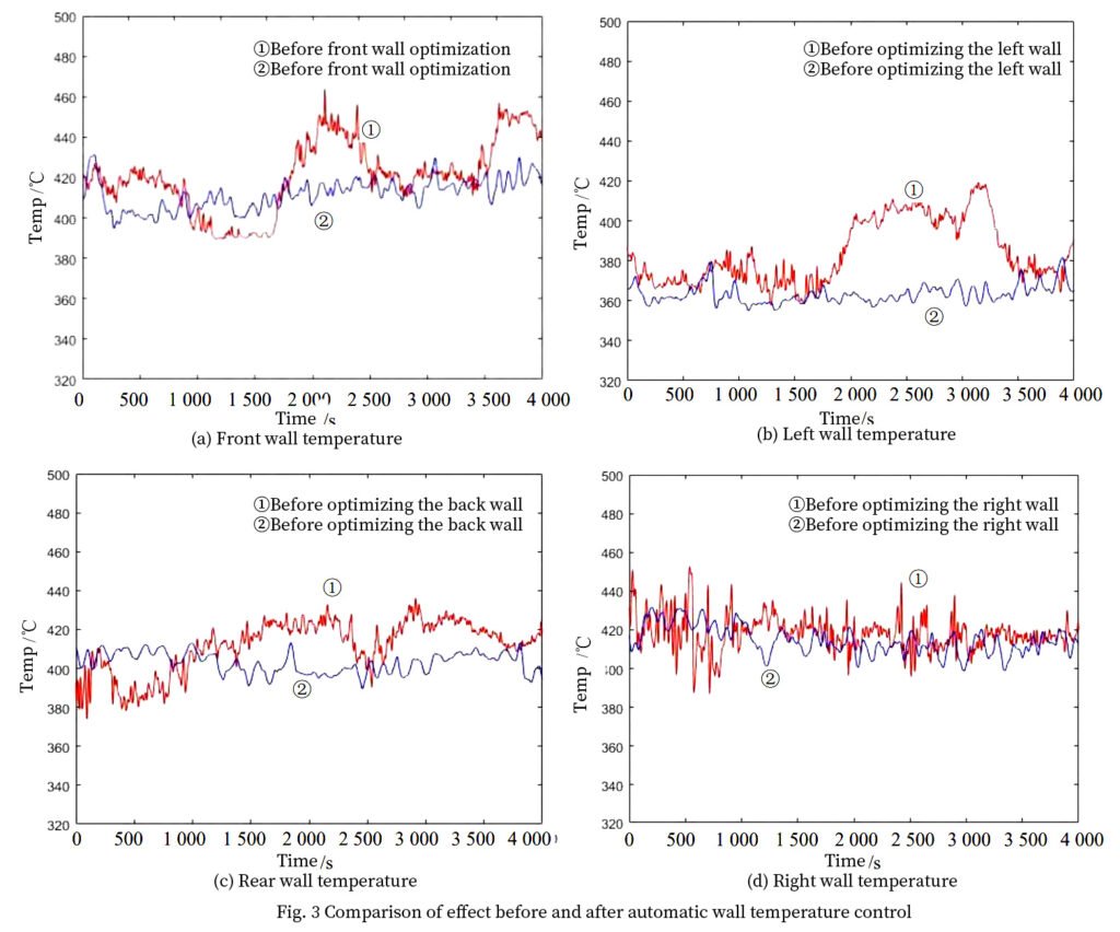
Temperature Variations Under Medium and Low Loads: Before implementing our control system, under stable working conditions and medium to low loads, there were notable differences in wall temperatures. Specifically, the right boiler water wall section had significantly higher values (mainly points 121-169 and 283-328), with some points exceeding 400 ℃, deviating by over 40 ℃ compared to other points.
High Load Alarm: At high loads, points 745-777 on the left wall, points 105-185 on the right wall, and points 283-328 approached alarm values. When the overheating degree reached 30 ℃, certain points on the right wall soared above 440 ℃, with some reaching even higher temperatures.
Operator-Dependent Adjustments: Prior to the introduction of our control system, operators had to manually adjust the boiler wall temperature during combustion operations. This process demanded experienced operators, placing a significant burden on the operational staff.
Automated Control Solution: Once our wall temperature adjustment automatic control system was put into operation, it brought about significant improvements. When wall temperatures fluctuated, the system automatically adjusted the combustion dampers to control the furnace flame’s center position, thus regulating the water wall temperature. If any corner of the boiler’s wall temperature began to overheat, the system responded by automatically adjusting the corner’s combustion dampers, increasing secondary air rigidity. It also opened the embers door in that corner to push the flame center diagonally, reducing the risk of high wall temperatures caused by excessive flame heat.
Positive Outcomes: The impact of this automated control system was clear. Wall temperature issues on the front wall, left wall, back wall, and right wall of the boiler were effectively mitigated after its implementation. Wall temperature fluctuations were notably reduced.
In summary, our wall temperature regulation control system played a vital role in addressing high-temperature corrosion challenges and achieving more stable and controlled wall temperatures, ultimately enhancing the efficiency and safety of our boiler operations.
Conclusion
In conclusion, this paper introduces a method for regulating boiler water wall temperature to prevent over-temperature by controlling the position of the boiler flame center. This method is based on numerical analysis and calculations to determine the coordinates of the flame center position, which are represented as coordinate points, providing information about the combustion position within the furnace.
We’ve also discussed the reintegration of boiler water wall temperature measurement points, transforming chaotic data into simplified wall temperature coordinate data. These wall temperature coordinates effectively reflect the fluctuation state of wall temperatures in various sections of the boiler.
Our approach involves adjusting the opening degree of the combustion damper angle to control the position of the furnace flame’s center coordinates. This creates a closed-loop control system that influences the flame’s center position and subsequently regulates the wall temperature coordinates through air distribution. As a result, we’ve significantly increased the automation level of boiler water wall temperature adjustment during unit operation.
The practical impact of this system has been remarkable. It effectively addresses issues arising from irrational combustion leading to differences in boiler water wall temperature and temperature spikes. Since implementing this system, we’ve observed a decrease in temperature unevenness across the boiler water wall and superheater wall, reducing the risk of pipe bursts and enhancing the safety and overall economy of the unit.
In essence, our method brings about more precise and automated control of boiler wall temperatures, contributing to the improved performance, safety, and efficiency of our power generation unit.
DHB Boiler
Discover The Superior Quality And Cutting-Edge Technology Of DHB Boilers. Explore Our Range Of Biomass Boilers, Waste Heat Boilers, And More. Take Your Industrial Operations To New Heights With DHB Boiler.
