The implementation of energy-saving and emission reduction policies has raised higher requirements for energy conservation in power plants. Currently, various large-scale thermal power generation units are exploring energy-saving solutions such as increasing steam inlet parameters and lowering turbine exhaust parameters, but they face limitations from various factors, including metal materials and environmental temperatures [1]. Optimizing the thermal system to reduce various heat losses of power generation units has become an effective way to achieve energy efficiency. At present, the exhaust gas temperature at the rear of coal-fired power plants generally ranges from 120 to 130 ℃, while in circulating fluidized bed power plants, the exhaust gas temperature can be higher, typically around 150 ℃ [2]. The excessively high flue gas temperature from boilers results in a significant proportion of heat loss in various boiler losses. Recovering waste heat from the flue gas at the rear of the boiler can improve the thermal efficiency of thermal power plants.
There are many measures for recovering boiler flue gas waste heat, and expanding the heat exchange area of economizers and air preheaters in the boiler flue is relatively simple. However, in most cases, due to space limitations (small space in the boiler flue) or poor economic benefits, this measure is not widely adopted by power plants. In addition, a gas-to-gas heat exchanger can be installed to recover flue gas waste heat. After installing a gas-to-gas heat exchanger, the high-temperature flue gas from the rear flue is used to heat the clean flue gas after desulfurization and denitrification, thereby reducing the exhaust gas temperature. However, this method is not energy-efficient, and frequently opening and closing the gas-to-gas heat exchanger can have various negative impacts on the operation of power plants.
Installing a low-temperature economizer downstream of the flue between the dust collector and the flue gas desulfurization device not only has the advantages of simple structure and minimal impact on the thermal system but also can relatively reduce the consumption of coal and water [3]. The low-temperature economizer is generally installed at the rear of the boiler, and its water-side pipeline is connected to the condensate water system of the thermal system. The condensate water absorbs the waste heat of the boiler flue gas, lowers the exhaust gas temperature, and returns to the condensate water system after temperature elevation. When arranging the thermal system, consideration should be given not only to the low-temperature corrosion, ash accumulation, and wear of the low-temperature economizer but also to its impact on turbine extraction during operation. Low-temperature economizer systems with spiral finned tubes or H-shaped finned tubes are now widely used for waste heat recovery from flue gas at the rear of boilers. It is important to note that after installing a low-temperature economizer, the pressure loss on the flue gas side is too high, requiring higher output from the induced draft fan, and the fan before the retrofit may experience overload problems.
1. Utilization of Low-Temperature Economizers in Flue Gas Waste Heat Recovery
Low-temperature economizers commonly employ a partitioned cross-flow heat exchanger, utilizing three heat transfer processes: convective heat transfer between the heat transfer fluid and the wall, conductive heat transfer through the wall, and convective heat transfer between the cold fluid and the wall. Specifically, the heat exchange on the working fluid side of the low-temperature economizer involves forced convection heat exchange inside the tube slots, while on the flue gas side, it is characterized by external forced convection heat exchange.
Typically, low-temperature economizers are installed at the rear of boiler flues. Condensate water is either entirely or partially drawn out, passing through the low-temperature economizer to absorb waste heat from the boiler flue gas. After temperature elevation, the condensate water returns to the condensate water system. On one hand, this process reduces the exhaust gas temperature, diminishing boiler exhaust heat losses. On the other hand, the heated condensate water, while maintaining a constant feedwater temperature, allows for a relative reduction in low-pressure extraction, enabling the steam turbine to perform more work and enhancing the thermal efficiency of the power plant [4].

2. Connection Methods of Low-Temperature Economizers to the Thermal System
The connection of low-temperature economizers to the piping system introduces significant differences in thermal calculation and thermal economy for the reheating system. The impact of the low-temperature economizer system on the entire condensate water system varies significantly depending on the connection method, generally classified into series, parallel, and mixed connections.
2.1 Series Connection
Condensate water is entirely drawn out from the outlet of a certain low-pressure heater, passing through the heat exchange surface of the low-temperature economizer for flue gas heat exchange and heating. After temperature elevation, it returns entirely to the inlet of the next low-pressure heater. In terms of the flow direction of condensate water, the added low-temperature economizer is in series between two low-pressure heaters, forming an essential part of the condensate water system.
In this connection method, all condensate water passes through the low-temperature economizer for heating, leading to a significant reduction in the exhaust gas temperature. The low-temperature economizer exhibits high efficiency, resulting in overall economic benefits. However, compared to the pre-installation scenario, condensate water must additionally pass through the low-temperature economizer’s pipeline, increasing the water flow resistance in the condensate water system. This necessitates an increase in the head of the condensate water pump. Additionally, in case of a economizer malfunction, this connection method requires the entire condensate water system to be shut down for maintenance, which is less convenient.
2.2 Parallel Connection
The working fluid side of the low-temperature economizer draws condensate water from the inlet of the seventh low-pressure heater. Condensate water is split at the inlet of the seventh low-pressure heater, with one portion passing through the seventh low-pressure heater and another portion entering the low-temperature economizer through additional piping. After heating and temperature elevation in the low-temperature economizer, this part of the condensate water merges with the main condensate water at the outlet of the seventh heater. In the condensate water system, the added low-temperature economizer and the low-pressure heater form a parallel configuration. Depending on specific water temperature conditions, one or multiple low-pressure heaters can be parallel to the low-temperature economizer. In this connection method, due to the diversion effect, some condensate water may not pass through the parallel low-pressure heater but instead enters the low-temperature economizer for heating. The reduced resistance from diversion compensates for the increased resistance brought by the additional low-temperature economizer piping, requiring no significant additional head from the condensate water pump. Furthermore, in this connection method, the low-temperature economizer system operates as a completely independent bypass, facilitating shutdowns and maintenance while ensuring feedwater supply. However, this connection method leads to a decrease in water flow rate due to diversion, resulting in less-than-ideal flue gas cooling.
2.3 Mixed Connection
Condensate water on the working fluid side of the low-temperature economizer is drawn from two points: the outlet of the eighth low-pressure heater and the outlet of the seventh low-pressure heater. After mixing, the temperature of the condensate water lies between the temperatures of the two sources. The mixed condensate water, after heating and temperature elevation in the low-temperature economizer, returns to the condensate water system.
This mixed connection method combines the characteristics of both series and parallel systems. By controlling the proportion of condensate water introduced at two points based on temperature differences at each level of the low-pressure heaters in the condensate water system, the temperature of the condensate water entering the low-temperature economizer can be effectively controlled. This stable temperature significantly reduces the extent of low-temperature corrosion in the low-temperature economizer piping, extending the equipment’s service life. However, this connection method involves complex piping connections, introducing additional control parameters during operation. Moreover, compared to the first two methods, the inlet temperature of the low-temperature economizer is relatively higher in this case. To ensure effective utilization of flue gas waste heat, the heat exchange surface area should also be correspondingly increased.
3. Arrangement Methods of Low-Temperature Economizers
Within the rear flue of a boiler, various processes such as dust removal, desulfurization, and denitrification are carried out. Therefore, there are multiple ways to arrange low-temperature economizers in the flue.
3.1 Placement of Low-Temperature Economizer Before Dust Collector
This arrangement has the following characteristics:
- The boiler’s rear flue gas can be reduced by 20 to 30 ℃ through the low-temperature economizer [5]. As per the gas state equation, the reduced volume of lower-temperature flue gas leads to an increase in ash content per unit volume, significantly improving the efficiency of the dust collector. For newly constructed units considering the installation of a low-temperature economizer, the reduced flue gas volume after the economizer allows for a smaller flue section after design, reducing the consumption of construction steel and yielding substantial economic benefits.
- With the decrease in flue gas volume, the output of the induced draft fan and the desulfurization booster fan can also be reduced to some extent, further reducing power consumption and indirectly improving efficiency.
- For many power generation units equipped with wet desulfurization devices, when lower-temperature flue gas enters the desulfurization unit, there is less water evaporating during the desulfurization process, resulting in reduced desulfurization water consumption.
- Flue gas passing through the coil tubes of the low-temperature economizer without going through the dust collector contains a large amount of dust, causing potential issues such as ash accumulation, wear, and even blockage on the heating surface area of the low-temperature economizer.
3.2 Placement of Low-Temperature Economizer Before Desulfurization Unit
Another arrangement of the low-temperature economizer is to place it in the flue between the dust collector and the desulfurization unit. This arrangement has several notable characteristics:
- The flue gas experiences a certain temperature rise after doing work through the induced draft fan. Placing the low-temperature economizer after the induced draft fan and before the desulfurization unit allows for the efficient utilization of the temperature rise brought by the induced draft fan, enhancing the recovery and utilization efficiency of flue gas waste heat.
- The flue gas passing through the dust removal device will have a significantly reduced dust content. The working environment of the low-temperature economizer in this arrangement is much better than the first placement method, resulting in a substantial improvement in ash accumulation and wear issues on the heat exchange tubes, thereby reducing operational risks and difficulties.
- For power generation units equipped with wet desulfurization devices, this arrangement can also save desulfurization water to some extent.
- Since the low-temperature economizer is installed at the rear of the flue, it is farther from the main plant, increasing the length of the condensate water pipe from the low-pressure system. Relevant pumps need sufficient head to overcome pipeline resistance.
3.3 Segmented Placement of Low-Temperature Economizer
Another arrangement involves segmenting the low-temperature economizer, with part placed before the dust collector and another part before the desulfurization unit. This segmented arrangement combines the characteristics of the first two methods, offering a compromise between their advantages and disadvantages. It’s important to note that this arrangement’s design and piping layout for the economizer are complex, adding unnecessary operational difficulties.
Considering the three arrangement methods, the first method of placing the low-temperature economizer before the dust collector exhibits excellent performance in waste heat recovery efficiency, optimizing dust removal efficiency, reducing flue gas resistance, and increasing the overall boiler cycle thermal efficiency. However, issues such as ash accumulation, wear, and even fly ash blockage can be addressed through structural design considerations. Currently, placing the low-temperature economizer before the dust collector generally meets conventional design requirements and is a commonly adopted arrangement in domestic power plants.

4. Considerations for Installing Low-Temperature Economizers
4.1 Low-Temperature Corrosion
The low-temperature economizer’s condensate water temperature is relatively low, making it prone to low-temperature corrosion. In engineering practice, two methods are considered to prevent or mitigate low-temperature corrosion. Firstly, designing a reasonable low-temperature economizer system to control the wall temperature of the heating surface within an acceptable range, reducing the corrosion rate to an acceptable level. Secondly, selecting appropriate corrosion-resistant materials for the low-temperature economizer’s piping. For economizers placed at the entrance of desulfurization units, where the risk of acid corrosion is higher, materials with better corrosion resistance, such as stainless steel, alloy steel, and carbon steel treated with corresponding enamel, are recommended.
4.2 Accumulation of Ash and Wear on the Heating Surface
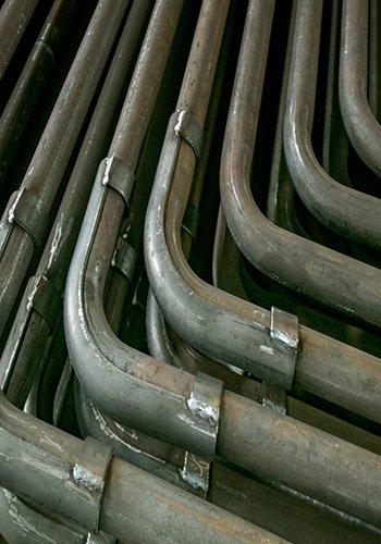
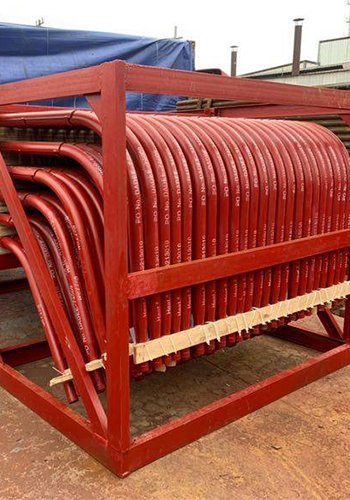
The heating surface of the low-temperature economizer consists of serpentine tubes connected between the inlet and outlet headers. The pipes of the low-temperature economizer can be light tubes, finned tubes, or spiral ribbed tubes. Non-light tube structures generally have better heat transfer area and efficiency than light tube-type low-temperature economizers. However, non-light tube structures are relatively complex, and problems such as ash accumulation and wear between ribs or fins may occur.
Engineering practice results indicate that the degree of ash accumulation on finned tubes is directly related to flue gas velocity and coal characteristics. Therefore, when designing the low-temperature economizer, it is essential to consider selecting an appropriate flue gas velocity and reasonable transverse and longitudinal tube spacing to reduce the likelihood of ash accumulation and wear. Ash content in boiler flue gas has various adverse effects on heat exchangers. Over time, ash content can contaminate the heating surface, increase fouling thermal resistance, impact heat exchanger efficiency, and in severe cases, lead to blockage of flue gas passages, increasing flow resistance on the flue gas side, causing uneven heating on serpentine tubes, and even affecting the boiler’s safe operation, leading to unplanned shutdowns and accidents.
To mitigate the impact of ash content on the heating surface of the low-temperature economizer, improvements are generally considered from two aspects. Firstly, when designing the low-temperature economizer, a higher flue gas velocity should be considered. To reduce wear on the tube wall from flying ash in the flue gas, wear-resistant heat exchange materials should be selected. The flue gas velocity should not be too high, generally requiring it to be greater than 10 m/s [6]. Secondly, the soot blowers of the low-temperature economizer should be arranged reasonably to ensure that they can blow on all heating surfaces when working, with no blind spots. When the soot blowers are in operation, adjusting the inlet flue gas baffle of the low-temperature economizer appropriately reduces the flue gas flow area, increases the flue gas velocity during soot blower operation, and improves the effectiveness of the soot blowers.
Conclusion
The installation of low-temperature economizers in large-scale thermal power plants effectively reduces flue gas temperatures, decreases water consumption in desulfurization systems, lowers coal consumption, and enhances economic benefits. Different water-side connection methods have their advantages and disadvantages. Placing the low-temperature economizer before the dust collector can generally meet conventional design requirements and is a commonly adopted arrangement in domestic power plants.
References
[1] Lin Wanchao . Theory of Energy Saving in Thermal Systems of Thermal Power Plants [M]. Xi’an: Xi’an Jiaotong University Press, 1994.
Xi’an: Xi’an Jiaotong University Press, 1994.
[2] Ye Jiangming, Pan Xiaojun, Chen Guanglie. Principles and equipment of power plant boilers [M]. Beijing: China Electric Power Press, 2010:
China Electric Power Press, 2010.
[3] Fan Quangui, Yan Weiping, Yan Shunlin, et al. Principles of boiler [M]. Beijing :China
China Electric Power Press, 2014.
[4] Li Qindao, Liu Zizhen. Calculation and Analysis of Thermal Economy of Thermal Power Plants [M]. Beijing: China Electric Power Press, 2008.
Beijing: China Electric Power Press, 2008.
[5] Liu Hezhong, Lian Zhengquan . Application of low-temperature coal economizer in thermal power plant [J].
J]. Electric Power Survey and Design, 2010(4):32-33.
[6] Xu Gang, Xu Cheng, Yang Yongping, et al. Deep utilization of power station boiler waste heat and tail
heating