Selective Catalytic Reduction (SCR) denitrification technology stands as a cornerstone in large and medium-sized coal-fired boilers for its remarkable denitrification efficiency and stable operation. However, the prevalent use of high dust arrangements in existing SCR denitrification devices poses challenges, particularly when combusting high ash coal. The elevated concentration of dust in the flue gas gives rise to issues such as ash accumulation and abrasion within the flue and internal components. This, in turn, leads to a decline in denitrification performance and an increase in operating resistance, significantly impacting the economic viability and stability of SCR denitrification systems.
Beyond the quality of the emitted smoke, the flow field characteristics of the system play a pivotal role in influencing ash deposition and wear within the denitrification device. A suboptimal flow field exacerbates ash deposition and wear issues, while proper fluid guidance serves as a deterrent to these challenges.
In high dust SCR systems, the economizer is positioned at the end of the SCR. The negative effects of high dust levels and inadequate flow guidance extend beyond the SCR system itself, affecting the economizer and causing wear-related problems. This article delves into the analysis of economizer wear issues in coal-fired units and proposes a solution to mitigate economizer wear at the end of the SCR through the optimization of the flow field.
By addressing the root causes of wear problems through flow field optimization, this approach aims to enhance the overall performance and longevity of SCR denitrification systems. The optimization not only safeguards against the adverse impact of high ash coal combustion but also ensures the sustained efficiency and stability of the economizer, thus contributing to the seamless operation of SCR denitrification technology in the face of challenging conditions.
Project Overview
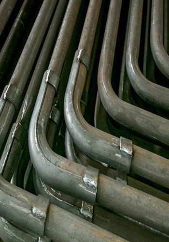
The coal-fired generating unit’s Selective Catalytic Reduction (SCR) back-end, specifically the tube bundle type economizer, is grappling with a severe wear issue. Since its commissioning, the unit has experienced numerous heat exchanger tube wear incidents, leading to leakage accidents that significantly jeopardize the safe and stable operation of the entire system. Through on-site surveys, it has been identified that the predominant wear occurs in the heat exchanger tubes, primarily concentrated on the flue side at the end of the SCR, as illustrated in Figure 1.

Wear Cause Analysis
To delve into the root causes of coal economizer wear, Computational Fluid Dynamics (CFD) has been employed to scrutinize the fluid dynamics characteristics of the system.
2.1 Physical Model
A three-dimensional model has been constructed, spanning from the bottom of the second catalyst layer of the SCR reactor to the outlet of the economizer, as depicted in Fig. 2.

2.2 Numerical Method
Hexahedral structural meshing was implemented with a size spacing of 100~120 mm, resulting in 1,890,002 grid cells. The grid count was further increased to 2,824,220, with negligible impact on results. The Discrete Phase Model (DPM) simulated dust particles, the K-ε model handled turbulence, and the porous media method was applied to the catalyst and economizer. The commercial software FLUENT solved the control equations using the SIMPLE algorithm, with second-order windward discretization. Convergence was deemed achieved when the residual values of all discretized equations were less than 10-4.
2.3 Calculation Results
1) Flow Velocity Distribution:
Figure 3 illustrates the velocity distribution of the flue gas trace from the SCR tail flue to the economizer outlet and the cross-section of the economizer inlet. Notably, a flow separation phenomenon occurs at the SCR tail flue turn, causing a gathering of separated flue gas at a specific distance from the right side of the heat exchanger tube bundle. This results in a significantly higher flue gas flow rate in the right area of the heat exchanger inlet section compared to conventional heat exchanger flues.

2) Ash Concentration Distribution:
Figure 4 depicts the ash concentration distribution in the flue cross-section and the economizer inlet section. Due to gravity, dust particles settle at the bottom of the flue, leading to higher concentrations. Moreover, a concentration of dust particles is observed at the flue bend at the end of the SCR, with a significant concentration on the right side of the economizer cross-section center.

3)Wear rate.
The wear of the heat exchanger was quantitatively analyzed based on the DPM erosion model. The discrete term rebound coefficients are related as follows.
Normal: yn= 0. 993-0. 0307x1+0. 000475x2-0. 00000261x3 (1)
Tangential: yt= 0. 993-0. 0307x1+0. 000475x2-0. 00000261x3 (2)
where: yn and yt are the bounce coefficients of the normal and tangential discrete terms, respectively; x1, x2 and x3 are the reflection angles of the corresponding nodes, respectively. Figure 5 shows the wear rate on the upper surface and centerline of the heat exchanger tube under the Generic model. Under the influence of high flow rate and high ash concentration, the pipe wears most seriously at about 2.5 m from both walls, and the maximum wear rate reaches 1.6×10⁻⁶kg/(m2-s).

Design Optimization
3.1 Optimization
To address the prevalent wear and tear of the heat exchanger tube caused by the high-velocity zone near the tube and the accumulation of ash particles, optimization measures are implemented in the SCR outlet area to redirect the flow. As illustrated in Figure 6, the addition of new deflectors (Deflector 1 and Deflector 2) alters the flow of flue gas at the end, slowing down the collection of dust. Furthermore, a tube bundle rectifier is introduced at the corner to enhance the uniformity of flue gas distribution and reduce the velocity of dust particles.

3.2 Optimization Results
1) Flow Rate and Ash Concentration Distribution:
Figure 7 displays the optimized velocity and dust concentration distribution in the upper 100 mm section of the economizer. The inflow optimization enhances the spatial uniformity of flue gas and dust distribution, mitigating concentration in specific areas. The maximum velocity and dust concentration in the cross-section are both reduced, with the maximum velocity dropping from 18.8 m/s to 15.3 m/s and the maximum dust concentration decreasing from 0.198 kg/m3 to 0.192 kg/m3. Notably, the change in maximum velocity positions towards the edge in Figure 7a is advantageous for reducing wear on the intermediate heat exchanger piping.

2) Wear Rate:
Post-optimization, the erosion rate on the heat exchanger tube surface and centerline is depicted in Figure 8. Figure 8a illustrates a significant reduction in the wear rate after optimization. Quantitative data (Figure 8b) reveal that the maximum wear rate on the optimized pipeline decreases from 1.6×10⁻⁶ kg/(m2.s) to 1.52×10⁻⁷ kg/(m2.s), signifying a substantial alleviation of the initial wear problem.
These optimization measures not only improve the overall performance of the system but also address the wear-related challenges faced by the coal-fired generating unit’s SCR back-end tube bundle type economizer, ensuring a more sustainable and reliable operation.
Conclusion
In the original design, a notable challenge was identified wherein the flue gas flow rate was high, and the concentration of dust particles was significant in the region approximately 2.5 m from the right wall. This led to a pronounced wear problem in the specified area, with the calculated maximum wear rate in the simulation reaching 1.6×10⁻⁶ kg/(m2.s).
Following the optimization of the inflow, there was a clear suppression of flue gas and dust concentration, resulting in a reduction of the maximum flow velocity at the heat exchanger inlet section from 18.8 m/s to 15.3 m/s. Additionally, the maximum dust concentration decreased from 0.198 kg/m3 to 0.192 kg/m3. The wear problem was effectively mitigated, and the maximum wear rate decreased significantly from 1.6 × 10⁻⁶ kg/(m2.s) to 1.52 × 10⁻⁷ kg/(m2.s). This represents a substantial improvement, reducing the maximum wear rate from 1.6 × 10⁻⁶ kg/(m2.s) to 1.52 × 10⁻⁷ kg/(m2.s).
The optimization measures successfully addressed the wear-related challenges in the coal-fired generating unit’s SCR back-end tube bundle type economizer. The enhanced design not only improves system performance but also ensures a more sustainable and reliable operation over the long term.