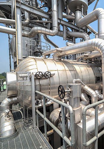
An economizer is a crucial component positioned at the rear of the boiler convective flue, designed to harness the residual heat from flue gas to heat the water. Its primary purpose is to reduce the exhaust gas temperature, thereby enhancing the boiler’s thermal efficiency. This article focuses on the economizer system employed in the five boilers at the Grand Thermal Power Plan
Description of Economizer Configurations:
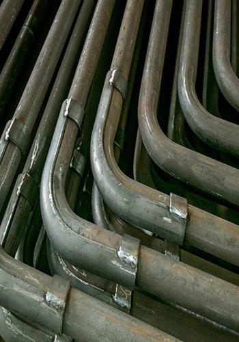
Among the five boilers currently in operation at the plant, boilers 1, 2, and 3 are equipped with single-stage economizers located in vertical shafts at the rear. The water and flue gas flow in counter-current, arranged in a staggered manner. The flue gas exit temperature is approximately 320°C, with a design velocity of 7.2 m/s. On the other hand, boilers 4 and 5 have economizers positioned in the rear flue duct. These economizers adopt a counter-current, two-stage arrangement with a staggered structure. The tubes are serpentinely arranged with specifications of Φ32×4mm and made of 20G steel. The exit temperature of flue gas from the upper-stage economizer is 374°C, while the lower-stage exit temperature is 267°C, and the flue gas velocity is 7.1 m/s.
Operational Challenges:
In recent years of operation, frequent instances of forced shutdowns due to economizer leakage have been observed. Each shutdown not only disrupts overall power generation, heating, and steam supply tasks but also incurs long downtimes and high costs. Additionally, such incidents contribute to the overall wear and tear of the boiler equipment, shortening its operational lifespan.

Significance of Economizer Protection:
Given the impact of economizer-related issues on operational continuity and cost-effectiveness, the significance of protecting the economizer to minimize leaks and reduce shutdown frequency during operation cannot be overstated. Strategies to enhance economizer reliability and prevent leakage are imperative for the sustained and efficient performance of the entire thermal power plant.
Analysis of Economizer Leakage Causes:
Economizer leakage in pulverized coal furnaces is primarily attributed to several factors: fly ash abrasion, internal corrosion of tubes, low-temperature corrosion, and over-temperature tube bursting. Fly ash abrasion results from the impact and cutting action of particles carried in the flue gas. Internal tube corrosion occurs due to elevated levels of oxygen in the feedwater and the precipitation of dissolved oxygen upon heating. Low-temperature corrosion is caused by the reaction of sulfur oxides and nitrogen oxides in the flue gas with water vapor, leading to acid corrosion. Over-temperature tube bursting is a consequence of localized overheating and inadequate cooling.
In the recent incidents of economizer leakage at the Grand Thermal Power Plant, most occurrences were observed in the serpent-shaped tube rows near the economizer’s rear wall and on both sides adjacent to the furnace wall – locations prone to common wear and tear. Leakage from the serpent-shaped tube rows near the rear wall is attributed to a significant accumulation of ash particles in the flue gas behind the economizer’s rear wall. This accumulation is a result of the flue gas making a 90° turn from the horizontal flue to the vertical flue, causing centrifugal forces to gather ash particles on the rear wall of the vertical flue. The high ash content in this section leads to severe abrasion in the rows of serpent-shaped tubes near the rear wall, ultimately causing leakage.
Furthermore, the gap between the bends in the economizer tubes and the walls of the vertical flue on either side can form a flue gas corridor. Due to minimal resistance, the high-speed flow of flue gas in this corridor exacerbates abrasion. Hence, mitigating flue gas-induced wear on the economizer is a key challenge in preventing economizer leakage at our plant.
1.1 Wear Principles:
When the heating surface of the economizer is subjected to the scouring action of flue gas, it experiences the impact of fly ash particles with a certain speed and force. Each impact can cause varying degrees of damage, removing extremely tiny metal fragments from the tube wall. Continuous impacts progressively thin the tube wall, resulting in wear. There are two types of wear based on the angle between the direction of ash particle movement and the impacted surface: when ash particles impact the furnace tube at an angle close to 90°, a plastic deformation layer forms on the tube surface, resulting in impact wear. When impacted at an oblique angle, the impact force is divided into normal force and tangential force. Normal force causes impact wear, while tangential force causes cutting wear. The downstream impact causes scouring wear.
1.2 Mathematical Analysis of Wear Factors:
Factors influencing wear include fly ash concentration, flue gas velocity, and the abrasive properties of fly ash. The basic formula for tube wear currently used is:
J=CKηω3t[kg/m2]
where:
- C is a constant unrelated to flue gas velocity but related to the type of coal.
- ω is the velocity of fly ash (m/s).
- η is the impact rate of fly ash, η=f(K), where K is related to η.

- Phσh is the density of fly ash (kg/m²).
- υ is the dynamic viscosity of flue gas (kg/(m·s)).
- g is the acceleration due to gravity (m/s²).
- d is the diameter of the heated surface tube (m).
The relationship between K and η is illustrated in Figure 1.

【Figure 1】Relationship between K and η
From the formula, it is evident that wear is influenced by flue gas velocity, fly ash concentration, and the quantity of fly ash. The relationship of each factor to wear is as follows:
- Fly ash velocity: Wear is directly proportional to the cube of fly ash velocity. Higher flue gas velocity results in more severe fly ash abrasion.
- Fly ash concentration: Greater fly ash concentration leads to more frequent ash particle impacts, resulting in more severe wear.
- Coal characteristics: Higher ash content in coal corresponds to greater fly ash concentration in flue gas and, consequently, more severe wear.
- Ash characteristics: Coarser and harder ash particles in flue gas result in more severe wear.
- Tube bundle structural characteristics: Wear is more severe in staggered and parallel tube bundles under lateral flue gas scouring, whereas wear is reduced under longitudinal flue gas scouring.
- Fly ash impact rate: Factors such as larger fly ash particles, higher fly ash density, faster flue gas flow velocity, and lower flue gas viscosity increase the impact rate of fly ash, leading to more severe wear.
Improvement Measures:
2.1 Ensure Optimal Flue Gas Velocity:
Under normal operating conditions, the designed flue gas velocity for the economizer at our plant is 7.1 m/s. However, deviations from rated load are common during boiler operation. In such instances, it is essential to reduce the boiler’s combustion air intake proportionally, control the excess air coefficient appropriately, and lower the flue gas velocity to protect the economizer. As per formula (1), reducing flue gas velocity significantly decreases wear. However, the flue gas velocity should not fall below 5 m/s to avoid exacerbating ash accumulation on the heating surfaces, leading to reduced flue gas passage area, uneven distribution of flue gas velocity, and increased wear at various locations. Additionally, enhancing the effectiveness of economizer soot blowing to reduce ash accumulation and increase the passage area is crucial. It is advisable to avoid operating the boiler at overload conditions, as increased load elevates flue gas velocity, resulting in higher ash particle carry and intensified tube wall wear. Operators often attempt to lower exhaust gas temperatures during operation by increasing induced draft fan air intake, which can further aggravate economizer wear.
2.2 Reduce Ash Hardness:
The economizer operates in the rear flue duct where, with decreasing flue gas temperature, the hardness of ash particles increases. Ash particles start hardening when the fly ash temperature drops below 700°C. Unburned coal powder particles entering the rear flue duct have a hardness significantly greater than that of ash particles, causing intense wear on the tube walls. To minimize economizer wear, it is essential to control the fineness of coal powder entering the furnace and adjust combustion appropriately to prevent unburned particles from entering the rear flue duct. The power plant’s fan mill direct-firing pulverizing system, with only one set of coarse powder separators, experiences a decrease in the impact plate’s effectiveness and blockage in the return powder pipe over time, leading to increased coal powder fineness entering the rear duct. Establishing a comprehensive monitoring system to control the coal powder fineness at the fan mill outlet based on its operating characteristics can effectively reduce the amount of unburned coal powder and enhance boiler combustion efficiency.
2.3 Decrease Ash Content Entering the Rear Duct:
Due to the low flue gas velocity and temperature at the ash settling pipe, water vapor in the flue gas condenses, causing ash to adhere or even freeze. This often results in clogging of the ash settling pipe, preventing timely ash discharge and leading to increased ash content in the rear duct. Some fly ash may even swirl around the ash hopper, causing multiple impacts and wear on the tube walls. Installing electromagnetic vibrators on the ash settling pipe to prevent fly ash condensation and blockage and timely discharging accumulated fly ash into a trench can effectively reduce ash content in the flue gas, especially large-diameter particles, thereby minimizing impact and wear on the economizer.
2.4 Strengthen Soot Blowing:
Accumulated ash in the economizer can hinder heat transfer, impede flue gas circulation, cause temperature deviations, uneven flue gas velocity, and increase the power consumption of the induced draft fan. Typically, ash accumulation in the economizer begins on the windward and leeward sides of the pipes and gradually expands, ultimately forming a blockage in the flue gas passage. The currently used soot blowing device at our plant has a radiation direction of semi-circular or elliptical shape with an effective radius of less than 3 m, which is insufficient to remove accumulated ash horizontally in the economizer. By installing shock wave soot blowers in the rear flue duct, using compressed air to blow ash horizontally, the soot blowers can effectively prevent the accumulation of fly ash and enhance economizer performance.
Conclusion
The economizer stands as an indispensable component in industrial boilers, and economizer leakage has become a significant factor impacting the normal operation of boilers. Therefore, protecting the economizer and minimizing the frequency of leaks and shutdowns are of paramount importance in achieving energy efficiency and emissions reduction. Based on the analysis of economizer leakage incidents at the Grand Thermal Power Plant in recent years, this article has proposed a series of improvement measures. These measures aim to enhance the overall performance of the economizer, ensuring its reliable operation and contributing to the broader goals of energy conservation and emissions reduction. Implementing these improvements will not only optimize boiler efficiency but also extend the operational lifespan of the economizer, ultimately promoting sustainable and environmentally responsible industrial practices.