Circulating fluidized bed combustion of coal is a relatively new coal-burning technology that has emerged in the last couple of decades. It stands out as one of the most advanced and widely adopted clean coal combustion methods in the industrial sector. This technology operates by utilizing fluidized combustion and consists primarily of two key components: the combustion chamber (comprising dense-phase and dilute-phase areas) and the circulation back to the furnace (which includes a high-temperature gas-solid separator and a recharge system).
One of the notable distinctions between circulating fluidized bed combustion and the traditional bubbling fluidized bed combustion technology is the considerably higher operating wind speed. This design emphasizes enhanced combustion efficiency and supports various non-homogeneous reaction processes such as denitrification and desulfurization. This marks a significant departure from the conventional laminar combustion (commonly known as chain furnaces) and suspended combustion (typical of pulverized coal furnaces) technologies.
The circulating fluidized bed boiler (CFB Boiler) boasts several remarkable advantages, including its ability to adapt to a wide range of fuel types, its flexibility in adjusting the load, and its comprehensive utilization of ash, among other favorable characteristics. These strengths have been fully demonstrated through the successful domestic operation of CFB boilers.
However, as environmental concerns grow increasingly prominent and national emissions standards for power plants become more stringent, there is a growing need for new environmental protection measures. Strict control of NOx emissions has become essential, but the high costs associated with tail-end denitrification make it imperative to swiftly develop and implement large-scale, low-NOxcombustion technology with high reliability in circulating fluidized bed power plant boilers. The time is ripe for this innovative solution.
The DFG-150/9.8-M high-temperature and high-pressure CFB boiler is an impressive piece of technology, developed by Jiangsu Huineng Heavy Industry Co., Ltd. for Ningbo Economic Development Zone Thermal Power Co., Ltd. This boiler, operating at a capacity of 150 t/h, represents the third generation of CFB (Circulating Fluidized Bed) technology. Its significance is immense, contributing to the advancement of coal-fired power generation and heating, reducing atmospheric pollution, and promoting energy efficiency. It also serves as a cutting-edge prototype in the boiler industry.
Here are the key principles followed in designing and manufacturing this 150 t/h class third-generation CFB boiler:
- Proven Components: The boiler incorporates combustion equipment, separation devices, and reclamation systems with a successful track record of long-term operation.
- Front Wall Coal Feeder and Soot Cooler: These components, known for their reliability, have been incorporated into the design based on extensive operational experience.
- High-Momentum Secondary Air Outlet: The use of a large-diameter, high-momentum secondary air outlet arrangement has been validated through long-term operation.
- Ignition Combustion Cylinder Entry: A reliable primary air back-wall ignition combustion cylinder entry arrangement ensures safe and efficient ignition.
- Anti-Wear Measures: Robust anti-wear measures have been implemented to ensure safe and trouble-free operation.
- Mature Design: The design emphasizes a mature and reliable expansion seal structure, a compact and aesthetically pleasing layout, and efficient boiler operation.
- Efficiency Optimization: The goal is to maximize boiler efficiency, reduce dust, NOx, and SO2 concentrations, and minimize energy consumption.
- Lower Fan Power: Efforts have been made to reduce the pressure head for the first and second winds, resulting in lower fan power requirements and energy savings.
- User-Friendly: The boiler boasts a simple structure, facilitating easy installation, operation, and maintenance, prioritizing user convenience.
After nearly six months of operation, the boiler has proven itself in various aspects, including its adaptability to a wide range of fuels, high combustion efficiency, load adjustment flexibility, low power consumption, and minimal emissions of NOx and SO2 pollutants. Users have praised its safe and reliable operation.
In March 2021, the China National Special Equipment Testing and Research Institute (National Boiler and Pressure Vessel Quality Supervision and Inspection Center) conducted environmental protection and energy efficiency tests on this 150 t/h third-generation CFB boiler. The test report affirmed that the boiler’s performance met the design requirements, further cementing its position as a groundbreaking technology in the field.
Main key Technologies of CFB Boiler
Here are the main key technologies incorporated into the CFB boiler’s design:
- Low-NOx Environmental Protection: The design prioritizes meeting stringent low-NOx environmental standards, while also focusing on high efficiency, energy savings, and overall reliability.
- High-Efficiency Separator: The design of the high-temperature steam-cooled separator emphasizes specific ratios, such as the inlet width to height (0.2), center cylinder to diameter (0.44), and height of the center cylinder inserted into the flue (0.25). These ratios ensure both high separation efficiency and reduced flue-gas resistance within the separator.
- Air Distribution System: The air cap receiver features unequal spacing, variable resistance design, and a structure that balances air resistance in different parts of the bed. The slag discharge opening of the air cap is designed to blow upward to prevent slag from spraying. Cold testing of the air distribution board includes a 200 mm thin material layer test to verify the air cap receiver’s variable resistance design against actual conditions, with adjustments made if necessary.
- Secondary Air System: This system employs a single-layer arrangement with a limited number of nozzles generating substantial momentum. The nozzles achieve wind speeds of up to 90 m/s. Additionally, the design includes variable diameter pipes in the small duct section to gradually accelerate wind speed from 20 m/s to 90 m/s, enhancing secondary air stiffness and penetration into the material layer. Four small secondary air ducts on the side of the front and back walls are angled toward the center to address oxygen deficiency in the chamber.
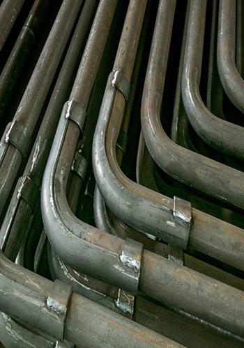
- Coal Feed Pipe: Utilizing patented technology, the coal feed pipe incorporates a large inclined angle. This design, combined with controlled coal feed wind, air cushion wind, coal broadcast wind, and sealed wind, ensures unobstructed coal flow and prevents flue gas from backing up.
- Lower Air Preheater: To prevent low flue gas temperatures in the lower air preheater and the associated issues of sulfuric acid and ammonia conversion, the design includes pitch adjustments in the lower tube box and spoiler-equipped tubes. This configuration maintains a clear path for flue gas, prevents ash solidification, and keeps flue gas temperatures within acceptable limits during extended boiler operation.
- Flue Gas Recirculation: A flue gas recirculation system, complete with a dedicated fan, is designed to control NOx emissions during boiler startup and coal feeding. By regulating the amount of flue gas entering the primary hot air ducts based on oxygen levels, the system maintains control over the original NOx emission concentration.
- Soot Chiller System: For stable and safe low-load boiler operation, a soot chiller system is implemented. This system discharges a portion of the circulating ash from the reclaiming box device, reducing furnace chamber differential pressure and increasing bed temperature when the boiler operates at low loads.
- Flue Gas Temperature Control: To ensure optimal flue gas temperature when the load is low, a water bypass system is integrated into the upper stage economizer. This system adjusts the amount of water in the bypass to raise the flue gas temperature entering the denitrification destructor.
- Structural Design for Ultra-Low Emissions and High Efficiency: The overall structural design of the boiler takes into account the requirements for achieving ultra-low emissions of NOx and SO2 while maintaining high thermal efficiency.
These key technologies collectively contribute to the boiler’s exceptional performance, environmental compliance, and efficiency across various operational conditions.

Enhancements to Key Systems in the Third-Generation CFB Boiler
2.1 Coal feed design of the CFB boiler
In the design update of the third-generation CFB boiler, the coal feed system has undergone significant improvements to enhance safety and operational efficiency.
Square Drop Tube Structure: To promote better mixing of coal particles with bed material and increase the distance between the coal feed nozzle and the secondary air nozzle, the coal drop nozzle is strategically positioned lower, closer to the furnace’s central area. This, however, can create a safety concern due to the risk of reverse coal stringing. To mitigate this issue, a square drop tube structure is employed. Simultaneously, Huineng’s patented technology is utilized for the coal feed wind and sealing wind structure. This ensures uniform air pressure throughout the drop tube, preventing coal blockages and effectively controlling flue gas backflow.
Sealing Wind: To further combat back-scattering, a sealing wind system is introduced at the front end of the sloping section of the square coal drop tube. The sealing wind is angled at 80° to the ground, with the nozzles slightly directed toward the furnace. The sealing air nozzles are designed with both large and small heads to reduce along-travel resistance. These nozzles counteract the positive pressure in the furnace chamber, preventing it from reversing into the upper part of the drop tube.
Anti-Wear Technology: The bottom of the coal drop tube incorporates innovative anti-wear technology. An anti-wear plate and coal broadcast wind are structured in a step-like manner. As coal particles fall, they are blown away from the anti-wear plate’s impact area, reducing wear and extending its service life. Guard plates are added on both sides of the anti-wear plate, complete with fascias at the ends to prevent deformation.
Coal Sowing Wind: The coal sowing wind within the coal feeding pipe is pressurized through a windbox. Positioned parallel to the anti-wear plate at the front of the coal drop tube, the coal sowing wind’s mouth is set at 20 mm height, while the back end of the windbox is elevated by 100 mm. The windbox’s top receives primary hot wind through a φ159 mm duct, propelling coal particles a considerable distance through the pressurized coal sowing wind. The 30 mm height difference between the anti-wear plate and the coal sowing wind ensures larger particles are expelled without contacting the bottom plate. This setup effectively acts as an air cushion while distributing coal.
Optimized Coal Particle Distribution: Ideally, coal particles are fine and uniform at around 10 mm. The coal fallout bottom plate directs coal at a horizontal angle of 30° to uniformly distribute it into the furnace chamber through the coal sowing wind. In practice, larger coal particles are common, causing an adjustment of the bottom plate angle to approximately 25°. This modification enhances even coal distribution. Furthermore, the coal broadcast wind employs pressurized nozzles, aligning its angle with the coal fallout angle, ensuring coal broadcasting is in line with the anti-friction plate. This fine-tuning enhances uniformity.
Controlled Coal Drop Opening: To prevent reverse cascading, the size of the coal drop opening is carefully regulated. Since positive pressure in the furnace acts uniformly on the furnace wall and the drop opening is recessed in the wall, it experiences lower pressure. This can lead to reverse cascading without external wind sources. To address this, the size of the coal drop opening is reduced, effectively controlling positive pressure. The design incorporates a wear plate at the bottom of the drop opening, adds lateral wear plates of 100 mm height on the side flanks, and installs reinforcement plates on the side flank wear plates. This configuration allows precise control of the coal fallout size, ensuring it remains slightly larger than 50 mm horizontally.
These enhancements to the coal feed system contribute significantly to the safety and efficiency of the third-generation CFB boiler, minimizing issues related to coal handling and distribution within the furnace.
2.2 Revamped Design of the Secondary Air System
In the layout of the secondary air system for CFB boilers, two critical objectives must be met: achieving graded combustion effectiveness and ensuring the penetration of secondary air into the bed while timely replenishing oxygen to the furnace’s central area. Drawing from years of boiler design and commissioning experience, a fresh approach is applied to the third-generation CFB boiler’s secondary air system:
(1) Single-Layer Nozzle Arrangement: The secondary air nozzles are organized in a single-layer configuration, strategically positioned at a height of 3.5 meters from the air distribution plate. This arrangement follows the principles of fewer nozzles with larger diameters, more centrally located, and fewer on the sides. Four nozzles on the sides are tilted toward the furnace’s center. Within the duct, wind speed gradually accelerates from 20 m/s to 90 m/s, imparting high rigidity to the secondary air and enhancing its penetration into the material layer. Recognizing the oxygen deficiency in the furnace’s central chamber in CFB operation, the design incorporates a tilt in the front and back walls of the secondary air ducts and the small ducts toward the center, effectively augmenting oxygen supply to the central chamber.
(2) Extended Accelerating Sections: All secondary air ducts feature elongated accelerating sections at their fronts, shaped as large and small heads. This design modification enhances the rigidity and effectiveness of the secondary air delivery.
(3) Optimized Calcium Spraying Interface: To capitalize on the principle that low initial SO2concentrations correspond with high oxygen levels, an interface for calcium spraying within the furnace is positioned within the secondary air ducts. Below the secondary air nozzle, a reduction area of the dense-phase bed, characterized by low initial NOx concentration, is established. Above the nozzle, an oxygen-rich area with low initial SO2 concentration is created. This innovative configuration effectively reduces the initial generation of both NOx and SO2, delivering dual environmental benefits.
These design updates to the secondary air system not only enhance combustion efficiency but also contribute to the mitigation of NOx and SO2 emissions in the third-generation CFB boiler.
2.3 Harnessing Flue Gas Recirculation for Emission Control
During the startup of coal-fired CFB boilers, the temperature of the flue gas at the furnace outlet typically falls within the range of 450~700 ℃. Unfortunately, this temperature range does not align with the temperature window required for SNCR (Selective Non-Catalytic Reduction) denitrification. Consequently, the original NOx emissions far exceed the permissible standards, often resulting in fines from local environmental agencies. This challenge has been a significant concern for thermal power plants nationwide.
To address the issue of excessive NOx emissions during boiler startup and coal feeding, a flue gas recirculation system has been implemented. This system incorporates a dedicated recirculation fan. The flue gas recirculation system leverages low-oxygen flue gas from the tail end instead of oxygen-rich air. This approach not only ensures thorough fluidization of the furnace bed material but also plays a pivotal role in reducing the oxygen content, thereby inhibiting the formation of nitrogen oxides (NOx). Consequently, this allows for control of the original NOx emissions within the range of 150~200 mg/Nm3.
In the flue gas recirculation system, the recirculation fan employs 304 stainless steel material to prevent corrosion due to the corrosive nature of flue gases. 304 stainless steel is known for its resistance to both acids and alkalis, making it a suitable choice for this application. The system connects from the induced draft fan outlet to a 304 stainless steel pipe leading to the flue gas recirculation fan’s inlet. Another 304 stainless steel pipe then connects to the primary air outlet duct box. An oxygen meter is strategically placed on the primary hot air duct box. During the boiler startup process, the system regulates the amount of flue gas entering the hot air duct box by monitoring changes in oxygen levels. The mixture of flue gas and primary hot air is directed into the water-cooled air chamber and subsequently into the air distribution plate cap, ensuring that the flue gas-air mixture is fully fluidized and well-controlled, thus mitigating flue gas corrosion. This meticulous approach ultimately results in a reduction of the original NOx emissions concentration.
Furthermore, since the boiler typically shares a chimney with other boilers, during the startup process, the other operational boilers increase the amount of ammonia spray water appropriately. This increment in ammonia spray water serves to lower the overall flue gas emission concentration. By collectively coordinating the efforts of multiple boilers sharing the same stack, the goal is to ensure that the total NOx emissions from all the stacks remain within compliance with regulatory standards.
The implementation of the flue gas recirculation system has significantly improved emission control during startup, addressing a long-standing concern in thermal power plants.

2.4 Coordinated Implementation of SCR System
To ensure the effective coordination of the SCR (Selective Catalytic Reduction) system within the third-generation CFB boiler, the following strategic measures have been introduced:
(1) Reserve Space for SCR Catalyst Installation: A 4.0m space is strategically reserved between the upper stage economizer and the intermediate stage economizer to facilitate the future installation of the catalyst. Given that the catalyst area requires a low flue gas velocity while the economizer area necessitates a high velocity, this design addresses the inherent contradiction. The horizontal space allocated for the catalyst is designed to be sufficiently large, effectively reducing the flue gas velocity in the catalyst area. This, in turn, ensures the longevity and optimal performance of the catalyst.
(2) Introduction of Water Bypass: A water bypass system is implemented between the outlet header box of the upper stage economizer and the inlet header box. Within this setup, a valve is incorporated to regulate the flow of water entering the serpentine tube of the upper stage economizer through the valve’s opening. This feature proves particularly useful during periods of low load or coal type variations. By controlling the water flow, the system maintains the temperature of the flue gas entering the catalyst within the required temperature window. When the boiler operates at a low load and the bypass valve is opened, the flue gas temperature at the upper stage economizer outlet can be raised by 10~15 ℃. This temperature adjustment enhances the reaction efficiency of the catalyst, ensuring optimal performance even under varying operating conditions.
These coordinated measures aim to maximize the efficiency and effectiveness of the SCR system, providing greater flexibility and control in managing flue gas temperature and catalyst performance.
2.5 Efficient Slag Discharge System for the Boiler
In the realm of circulating fluidized bed technology, much like the coal feed design, the selection of reliable ash cooling equipment is paramount to ensuring the unit’s long-term safe operation. The slag discharge system implemented in this project follows a meticulous process:
The bottom slag generated during coal combustion is efficiently discharged from the furnace through three water-cooled slag discharge pipes positioned at the base of the air distribution plate. Two of these pipes are directly linked to two water-cooled drum slag chillers. These specialized chillers play a crucial role in cooling the bottom slag to a manageable temperature before efficiently transferring it to the belt slag conveyor system.
A thoughtful aspect of the design involves positioning the slag discharge pipe closer to the back wall direction. This configuration increases the residence time of coal within the boiler. The extended residence time serves the purpose of reducing the carbon content within the bottom slag. By doing so, the system optimizes the disposal of bottom slag while promoting safe and efficient boiler operation.
2.6 Comprehensive Anti-Friction Measures for Boiler Durability
To ensure the reliable and long-term safe operation of the CFB boiler, it is imperative to implement a comprehensive anti-wear strategy. In CFB boilers, wear typically manifests as scouring and impact wear. These types of wear predominantly occur in specific areas, such as the dense phase region, high-velocity flue gas zones, and irregular tubes on the heating surface. Problematic locations include the lower part of the hearth, the separator inlet, the flue gas corridor, and openings for access doors along rows of convective heating surface columns.
The incorporation of dependable anti-wear measures begins with thoughtful design choices. First and foremost, the selection of a reasonable flue gas flow rate in the furnace is crucial. Additionally, the design includes a longer chamber section at the intersection of the dense phase and thin-phase areas, allowing for the water-cooled wall to exit at this juncture. This design feature ensures that the casting material in the bend area does not cause wear to the downstream water-cooled wall.
Another wear-prone area in the boiler is the corners of the water-cooled wall within the furnace chamber. To address this issue, the design of the third-generation CFB boiler incorporates a solution where wear-resistant plastic is applied to all four corners of the furnace chamber. This strategic application of wear-resistant material effectively mitigates wear on the water-cooled wall corners.
Moreover, high-temperature, high-flow velocity scouring areas, like the upper part of the furnace flue gas outlet, demand special attention. Here, the back wall and the upper side wall of the water-cooled wall against the back wall area are also coated with wear-resistant plastic. This additional layer of protection ensures that wear and tear caused by high-velocity flue gas is effectively managed, further contributing to the boiler’s longevity and reliability.
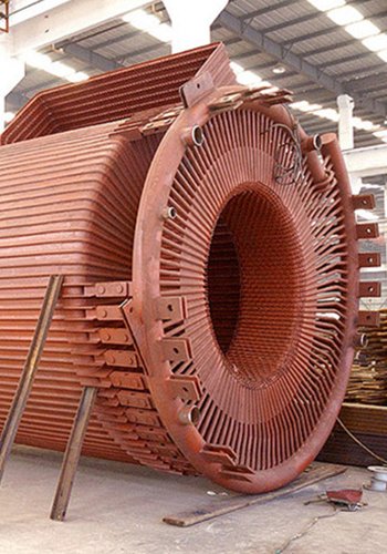
2.7 Enhanced Design of the Shell-Type Vapor-Cooled Cyclone Separator and Reclaimer
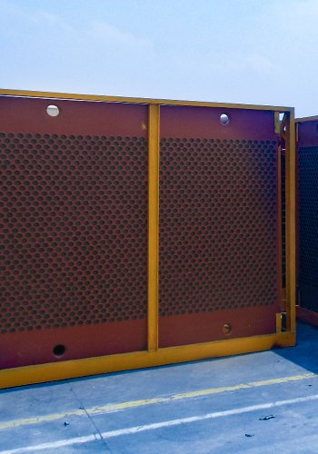
In the development of low-NOx combustion technology for CFB boilers in domestic boiler plants, there has been a focus on optimizing the separation efficiency of high-temperature cyclone separators. Typically, this pursuit has led to the selection of relatively high flue gas velocities at the separator inlet and outlet, along with a significant depth for the insertion of the center cylinder into the inlet flue. Consequently, the flue gas resistance within the high-temperature cyclone separator during boiler operation often exceeds 2,500 Pa. Additionally, the design of the air preheater tube box at the boiler’s tail end has often followed conventional CFB boiler standards.
However, this conventional approach has its drawbacks. Specifically, the distance between the tubes in the lower tube box of the air preheater is often relatively small, leading to high ammonia escape rates. Furthermore, within the lower tube box, flue gas reacts with SO3, producing ammonia hydrogensulphate. This substance, combined with ash particles, adheres to the tubes, forming a layer of ash slate. Over time, this buildup increases flue gas resistance, eventually reaching a point where the induced draft fan can no longer effectively pull the flue gas, necessitating forced furnace ash clearing.
To address the issue of high flue gas system resistance in the CFB boiler, optimizations have been made to the structure of the high-temperature cyclone separator and other key areas:
(1) High-Temperature Steam-Cooled Separator: The design of the high-temperature steam-cooled separator now features an inlet width-to-height ratio of 0.2, a center cylinder-to-cylinder diameter ratio of 0.44, and a center cylinder insertion height ratio of 0.25. This carefully considered design not only ensures a sufficiently high separation efficiency but also reduces the overall flue gas resistance within the separator.
(2) Reclaimer: The reclaimer has been enhanced with a three-chamber wind box, incorporating reclaim wind, conveying wind, and loose wind. Moreover, high-resistance reclaim-type wind caps and loose-type wind caps have been thoughtfully arranged to ensure smooth and efficient reclamation processes.
These structural optimizations work in tandem to mitigate flue gas resistance issues, ultimately contributing to improved performance and operational efficiency of the CFB boiler.
2.8 Air Cap Design for Efficient Air Distribution
The air distribution system in our CFB boiler is meticulously designed for optimal performance and efficient operation. The key elements of this system include:
- Unequal Spacing and Variable Resistance: The air cap receiver is designed with unequal spacing and variable resistance. This design feature helps balance the airflow distribution within the bed. In areas where the bed resistance is relatively low, the air cap receiver structure has smaller resistance, while in areas with higher bed resistance, the structure features larger resistance. This strategic design ensures that the airflow is appropriately distributed throughout the bed.
- Slag Discharge Considerations: The air cap holes at the slag discharge mouth are specifically designed to blow upwards. This unique configuration prevents the unwanted spraying of slag during the slag discharge process. This is essential for maintaining a clean and efficient boiler operation.
- Cold Testing for Verification: Before finalizing the design, cold tests are conducted with a 200 mm thin material layer. These tests serve to validate whether the variable resistance design of the air cap receiver aligns with the actual operational conditions. Any discrepancies or deviations found during these tests are promptly corrected, ensuring that the air cap receiver functions in accordance with the intended design.
By incorporating these design considerations, our air distribution system optimizes airflow, minimizes slag-related issues, and ensures the efficient and reliable operation of the CFB boiler.
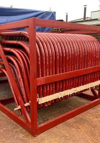
2.9 Innovative Coal Economizer Design for Enhanced Efficiency
To ensure that the flue gas temperature entering the denitrification destructor in the upper stage economizer reaches the optimal temperature window, even during low load operation, our design incorporates a water bypass system within the upper stage economizer inlet collector and outlet collector. This water bypass allows us to fine-tune the flue gas temperature by adjusting the amount of water in the bypass, ensuring it falls within the desired range.
Collaborating closely with catalyst manufacturers, we’ve also made improvements to the catalyst area. By increasing the cross-sectional area of the catalyst zone, we’ve effectively reduced flue gas resistance within the catalyst, optimizing its performance in the denitrification process.
Furthermore, in our design, we’ve strategically arranged the upper and lower economizers to provide ample space for the future installation of SCR (Selective Catalytic Reduction) denitrification equipment. This forward-looking approach ensures that the boiler can readily accommodate future upgrades or enhancements in emission control technology.
Through these innovative design choices, we’ve aimed to enhance the overall efficiency and adaptability of the boiler, especially concerning emissions control and low-load operation.
2.10 Innovative Design for Energy Efficiency, Desulfurization, and Low-NOx Combustion
In our pursuit of energy efficiency, emissions reduction, and improved combustion, our boiler design incorporates several innovative features.
Optimized Furnace Design: To achieve efficient combustion and maintain stability even at low loads (as low as 30% of capacity), we’ve optimized the furnace size and heating surface layout based on fluidized combustion theory. Additionally, we’ve modified the primary air inlet to come from the ignition burner, evenly distributing air through the back wall. This reduces primary air resistance while ensuring full bed fluidization, thus enhancing combustion stability.
Enhanced Secondary Air Arrangement: Our design includes a high secondary air arrangement. We’ve carefully positioned single secondary air openings with an eccentric design to intensify combustion in the central furnace area, reducing the presence of fly ash combustibles. This approach helps control NOx emissions and concentrates combustion intensity in the central region, thereby minimizing fly ash combustibles.
Self-Desulfurization Function: A notable advantage of CFB boiler technology is its ability to reduce SO2 emissions by introducing limestone into the furnace. Our third-generation CFB boiler adopts low-NOxcombustion technology and optimizes the heating surface arrangement to control the furnace’s combustion temperature between 850 to 890 ℃—an ideal range for in-furnace desulfurization. Given that coal often contains CaCO3 and MgCO3, when these compounds decompose at the optimal temperature range with the right amount of oxygen, they produce CaO and MgO, which react with SO2 in the flue gas. This self-desulfurization process can achieve a desulfurization rate of approximately 20% to 30%.
NOx Emissions Control: Compared to bubbling fluidized bed boilers, CFB boilers achieve lower NOx emissions primarily due to graded air supply. In our design, approximately 50% of the combustion air enters the lower part of the furnace chamber, creating a reducing atmosphere that inhibits NOx formation. The remaining 50% of combustion air enters from the upper part of the chamber, where the N component in the fuel naturally generates less NOxduring combustion. We’ve also considered fuel particle size, as studies have shown that larger fuel particles lead to higher NOx emissions. Therefore, we control the fuel particle size within a range of 0-10 mm, optimizing combustion and reducing NOx emissions.
Achieving Low-NOx Emissions: Our efforts have resulted in an initial NOxemission level of below 120 mg/m3 for a 150 t/h class third-generation CFB boiler. With the inclusion of SNCR (Selective Non-Catalytic Reduction) denitrification at the inlet of the cyclone separator, the NOx content in the exhaust flue gas can be easily maintained below 50 mg/m3. This design has been thoroughly tested and verified by the China Special Equipment Testing and Research Institute and the National Center for Quality Supervision and Inspection of Boilers and Pressure Vessels, with an impressive initial NOx emission of just 88.52 mg/m3.
Through these innovative design measures, we’ve successfully achieved a balance between energy efficiency, emissions control, and reliable combustion in our third-generation CFB boiler.
Summary
The third-generation CFB boiler offers distinct advantages that set it apart from other coal direct combustion technologies. Its key strength lies in its ability to achieve highly efficient combustion while rigorously controlling the generation of pollutants. This capability ensures that coal direct combustion aligns with the increasingly stringent environmental protection requirements. As a result, by investing in the research and development of industrialized boilers, we can introduce efficient and low-pollution coal combustion technology into the traditional boiler industry.
This infusion of advanced technology has the potential to enhance traditional industry products, facilitate product upgrades, and drive technological transformation within the industry. Furthermore, it plays an active role in promoting the development of related industries. In essence, the third-generation CFB boiler represents a significant step forward in addressing environmental concerns while simultaneously advancing the capabilities and sustainability of the broader industrial landscape.
[Source] Heqi, Third Generation CFB Boiler Technology,Academic Forum:123-126