Single- and Double-Layer Air Plates in Circulating Fluidized Bed (CFB) Boilers
As the scale of CFB boilers increases, so does the furnace size. This is exemplified in Table 1, which illustrates the cross-sectional area of the furnace in a 600 MW class CFB boiler reaching up to 418 m2. In the case of a furnace employing a single-layer fabric plate structure, ensuring effective penetration of secondary air jets necessitates an increase in the width-to-depth ratio. For instance, the 300 MW CFB boiler at the JEA power station in the United States has a width-to-depth ratio of 3.88. Computational findings from a numerical simulation of the 300 MW CFB furnace at the Baolite Power Station underscore that a higher width-to-depth ratio indeed yields advantageous results for enhancing the replenishment of center oxygen within the furnace. Similarly, numerical simulations conducted on the 300 MW CFB furnace at the Baolihua Power Station confirm the favorable impact of an increased width-to-depth ratio on optimizing secondary air distribution to augment oxygen levels at the furnace core.
Nevertheless, the elongated and slender furnace design presents challenges in terms of achieving uniform air distribution and consistent material fluidization on both sides. These challenges are often manifested as deviations in bed temperature and bed pressure on either side during operation. To address this, operational personnel typically implement adjustments in coal feed distribution to ameliorate the unevenness and ensure smoother operation.
Tab. 1 Furnace size of large-scale CFB boilers
| Plant | Power MW | Furnace mxmxm | Width to depth ratio | Cross-sectional area m2 | ||
| JEA | 300 | 26 | 6.7 | 35.1 | 3.88 | 174.2 |
| Baima | 300 | 15.1 | 12.6 | 35.5 | 1.20 | 190.3 |
| Baolihua | 300 | 28.3 | 8.4 | 40.0 | 3.37 | 237.7 |
| Fenyi | 330 | 25.8 | 9.5 | 39.0 | 2.72 | 245.1 |
| Lagisza | 460 | 27.6 | 10.6 | 48.0 | 2.60 | 292.6 |
| Baima | 600 | 27.9 | 15.0 | 55.0 | 1.86 | 418.5 |
Utilizing a Double-Plate Structure Hearth for Enhanced Secondary Air Penetration in Larger Furnaces
Addressing the challenge of insufficient secondary air penetration in larger furnaces involves an alternative solution: implementing a double-plate structure hearth (as depicted in Figure 6(b)). This approach has been successfully adopted in notable instances such as the 300 MW subcritical and 600 MW supercritical CFB boilers at the Baima Power Station. The distinct feature of this approach is the split configuration in the lower section of the hearth. By employing this design, the necessary range for secondary air introduction is significantly reduced, leading to improved combustion within the central region of the hearth.
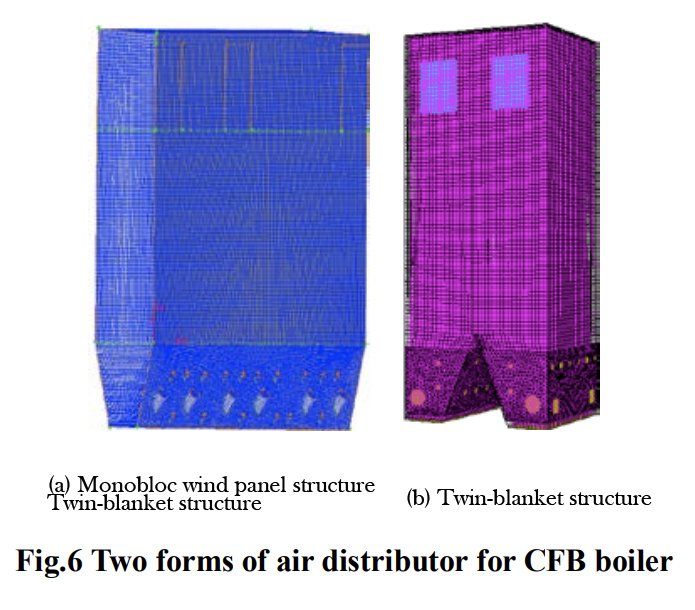
Empirical validation through cold modeling tests of the double-plate hearth has demonstrated that the axial distribution of particle concentration and the rate of external circulation flow in the furnace remain comparable to those observed in single-plate hearth configurations. However, it’s important to note that the implementation of a double-plate structure introduces a novel challenge: bed material overturning during operational phases. This phenomenon can have implications for the safe and stable operation of the boiler, requiring careful consideration and mitigation strategies.
Resolving Bed Overturning in Double-Plate Aircloth Hearths
Thorough theoretical and experimental investigations have pinpointed the root cause of the bed overturning phenomenon observed in double aircloth hearths. This phenomenon arises from a positive feedback loop between the air volume of the two sides of the aircloth plate and the resistance encountered by the material layer. Consequently, an effective preventive approach for actual boilers involves integrating control logic to adjust the fluidizing damper flap within the Distributed Control System (DCS) in response to discrepancies in fluidizing air volume between both sides.
Importantly, the occurrence of bed-over in double-blanket hearths is context-specific, typically manifesting under certain operational parameters, particularly at lower loads during furnace operation. Researchers have delineated the self-equilibrium zone of the double-blanket hearth through a combination of cold-modeling tests and theoretical analyses. This insight highlights that the bed-over phenomenon is not an inherent flaw in CFB boilers featuring the double-blanket hearth design. Moreover, under conditions where effective prevention of bed-over is achieved, the double-blanket hearth structure remains the optimal choice for larger CFB boilers.
Configuration of Multiple Cyclone Separators
In the context of larger Circulating Fluidized Bed boilers (CFB Boilers), the necessity for a parallel arrangement of multiple cyclone separators is evident. Figure 7 illustrates the configuration of separators within the Foster Wheeler and Alstom companies’ large-scale CFB boilers. Notably, the quantity of separators escalates proportionally with the augmentation of boiler capacity. Upon reaching a capacity of 600 MW, a typical arrangement comprises six separators. To ensure comprehensive structural coherence, the H-type furnace is generally employed, enabling the placement of separators on either side of the furnace. This arrangement is exemplified by the 600 MW supercritical CFB boiler at the Baima Power Plant.
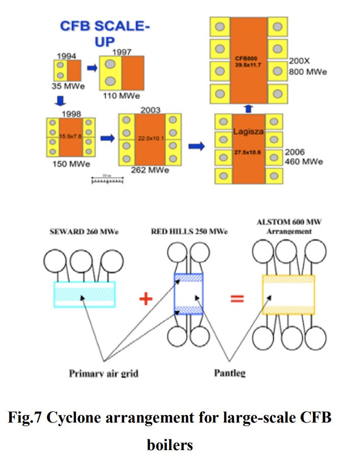
In the realm of large CFB boilers featuring multiple separators, a paramount concern pertains to the equitable distribution of flow between these separators. Given that the design of separators in large CFB boilers is meticulously tailored to align with parameters encompassing boiler flue gas volume and bed material circulation, any incongruity in the distribution of circulating materials amongst parallel separators will invariably deviate from the intended design conditions. This divergence can culminate in diminished separation efficiency, heightened carbon content in fly ash, and a subsequent decline in boiler efficiency.
The configuration involving multiple separators introduces a parallel channel multiphase flow scenario within the gas-solid two-phase system. Research has demonstrated that an imbalance in gas-solid flow distribution can arise when the number of separators exceeds two. The system’s stable state is intrinsically linked to particle concentration at the inlet of the separators. This observation is particularly relevant for CFB boilers of 300 MW and 600 MW capacities featuring over three separators on one side. Numerical simulations and modeling tests have consistently shown that the separator positioned centrally on the same side exhibits a higher material circulation flow rate compared to its counterparts on either side. Despite this, the overall flow distribution deviation remains within the confines of 5%. Consequently, the impact on individual separator separation efficiency and particle distribution within the furnace remains relatively constrained.
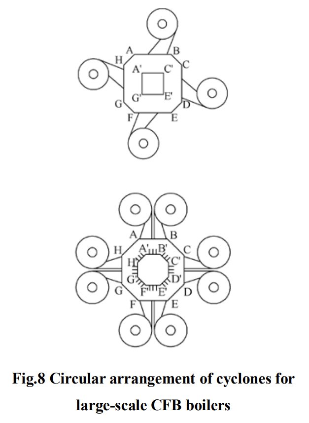
However, while the H-type arrangement comprising six cyclone separators in 600 MW class CFB boilers effectively addresses spatial and material distribution concerns, this arrangement is not without limitations. An inherent limitation exists in the scalability of this arrangement, and ensuring uniformity between same-side separators becomes increasingly challenging as the number of separators surpasses eight. In response, some scholars have introduced an innovative multi-separator arrangement, depicted in Figure 8. In this novel approach, the large CFB boiler chamber is configured in a ring shape, housing cyclone separators evenly distributed around the chamber perimeter. This arrangement enables a rational increase in the number of separators and offers the added advantage of enhanced secondary air penetration. However, akin to the previous configurations with large width-to-depth ratios, this chamber design presents analogous challenges such as uncertain air distribution diagonally across the hearth and the uniformity of fluidization. These aspects require further comprehensive study for conclusive understanding.
Heat Transfer in the Suspended Heating Surfaces of Furnaces
As the realm of large-scale Circulating Fluidized Bed boilers (CFB Boilers) advances, there emerges a concomitant expansion in the dimensions of furnace chambers. Ensuring the optimal heat balance within these furnaces necessitates strategic arrangements of heating surfaces within the primary circulation loop of the CFB boiler. These arrangements encompass the incorporation of suspension screens and partition walls within the furnace, alongside the integration of external heat exchangers within the solid particle circulation loop.
For instance, in the case of the 300 MW class CFB boiler at Dongnan, a total of 12 panels are employed within the furnace to facilitate heat transfer. Similarly, in the 300 MW class CFB boiler at Dongbu, the furnace chamber accommodates 12 superheaters, 6 reheaters, and 2 water-cooled panels, optimizing heat exchange. The pursuit of enhanced performance extends to the 600 MW supercritical CFB boiler developed by Dongbu, where the furnace chamber houses 16 suspension panels and 7 water-cooled diaphragm walls, further refining heat transfer dynamics.
Understanding the intricacies of heat transfer characteristics associated with these diverse heating surfaces is pivotal to the secure, efficient, and steadfast operation of large CFB boilers. Such comprehension underpins the realization of the boilers’ performance potential, ensuring both their operational safety and their capacity for optimal heat exchange.
An effective and pragmatic approach to delineate heat transfer coefficients involves an inversion process and empirical equation fitting, grounded in the actual operational parameters and flow rate data of large Circulating Fluidized Bed boilers (CFB Boilers). In this regard, Ling et al. conducted measurements of heat transfer coefficients on suspended heat receiving surfaces within two smaller CFB boilers, revealing an increase in values correlated with higher operating wind speeds. Additionally, Cheng et al. undertook an analysis of heat transfer coefficients for water-cooled walls and suspended screens in a 165 MW CFB boiler furnace. They adeptly employed empirical formulas to derive practical equations that encapsulate the observed heat transfer behavior.
However, to comprehensively comprehend the intricacies of heat transfer processes within the furnace, a reliance on a heat transfer model becomes indispensable. Unlike pulverized coal boilers, CFB boilers boast a distinctive ring-core flow structure within the furnace chamber, where convective heat transfer and radiative heat transfer are of equal significance on the heated surface. Wu Haibo et al. devised a heat transfer model that amalgamates classical radiant heat transfer principles to compute radiant heat transfer within the suspended screen of a CFB furnace chamber. Moreover, the model harnesses a functional equation involving flue gas velocity and material concentration to calculate convective heat transfer. Notably, the model’s foundation rests upon measured data from a 300 MW CFB boiler, employed for inverting the convective heat transfer equation. Consequently, the model attains a high degree of accuracy, especially within the same caliber of CFB boilers. This approach facilitates a nuanced understanding of heat transfer mechanisms and equips practitioners with a reliable tool for accurate calculations.
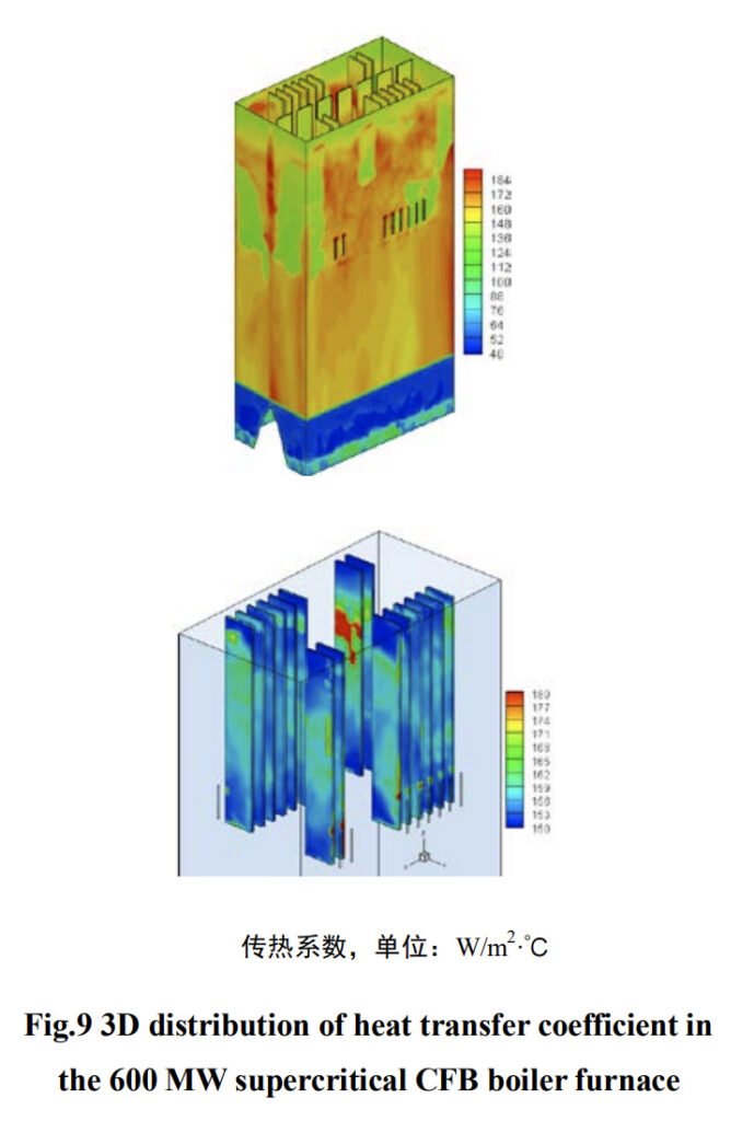
Acknowledging the significant radial non-uniformity of gas-solid flow within the furnace chamber of expansive Circulating Fluidized Bed boilers (CFB Boilers), conventional approaches relying on single-point lumped, zoned segments, or axial one-dimensional calculations fall short of meeting the intricate design requisites. Zhou Xinglong et al. have devised a sophisticated three-dimensional method for computing heat transfer coefficients on heating surfaces. This method capitalizes on the numerical simulation of gas-solid flow within the furnace, employing Euler’s two-fluid model. Moreover, it leverages the particle cluster updating model to calculate heat transfer coefficients on the furnace’s heating surface, alongside the density of heat flow within the three-dimensional furnace calculation.
One noteworthy application of this technique is evident in the three-dimensional distribution of heat transfer coefficients across the heating surface of the 600 MW supercritical CFB boiler chamber at the Baima Power Station, illustrated in Figure 9. By embracing this approach, it becomes feasible to effectively capture the mechanistic influence of gas-solid flow on furnace heat transfer coefficients. Consequently, this method holds remarkable significance in guiding the design of expansive CFB furnace hearths. Nevertheless, it’s important to acknowledge that, while validated within cold test beds, further scrutiny is essential to validate the accuracy of this calculation method when applied to the actual high-temperature operating conditions of a large CFB furnace. This underscores the potential for further research and refinement to solidify its applicability and accuracy.
The trajectory of Circulating Fluidized Bed boilers (CFB Boilers) is oriented towards increased dimensions and supercritical parameters. Through the accumulation of experience in independently developing 300 MW CFB boilers and successfully commissioning supercritical 600 MW CFB boilers, China has firmly established its large-scale CFB boiler technology on the global forefront. This success marks an opportune phase for the advancement of China’s CFB boiler technology, although it’s important to acknowledge that numerous challenges persist as large-scale developments unfold.
China is poised to capitalize on this opportunity by continuing the assimilation of foreign advanced technologies while simultaneously engaging in robust foundational research to foster indigenous technological advancements. This dual approach will enable China to sustain a trajectory of high-speed, stable, and robust growth in the realm of large-scale CFB boiler technology. As the industry continues to evolve, China’s endeavors in digestion, absorption, and independent innovation will serve as the cornerstone for maintaining its competitive edge and steering its large-scale CFB boiler technology towards a future characterized by dynamic, sustainable development.
[Source] ZHOU Xing-long, XIE Jian-wen, FAN Yong-sheng, WANG Bao-liang, HUANG Jun, Development And Research of Large-Scale Circulating Fluidized Bed Boiler
DHB Boiler
Discover The Superior Quality And Cutting-Edge Technology Of DHB Boilers. Explore Our Range Of Biomass Boilers, Waste Heat Boilers, And More. Take Your Industrial Operations To New Heights With DHB Boiler.
