Discover the path to heightened efficiency and durability in waste incinerators. Embark on a journey of transformation with advanced boiler heating surface upgrades.
The waste-to-energy facility has a nominal garbage treatment capacity of 750 tons per day along with an additional 75 tons per day for drying municipal sludge. The rated evaporation capacity stands at 90.8 tons per hour, while the maximum continuous evaporation capacity, considering 825 tons per day of garbage and 75 tons per day of drying municipal sludge, is 98.6 tons per hour. The primary steam operates at a pressure of 4.0MPa and a temperature of 450°C, with a feed water temperature of 130°C. The designed exhaust temperature falls within the range of 180 to 200°C. The anticipated low calorific value is 8195 kJ/kg. Despite being operational for four years, discrepancies between actual operational data and design specifications have arisen, highlighting the following issues:
- Elevated Smoke Temperatures: The smoke temperature preceding the superheater and evaporator exceeds the intended design parameters, leading to accelerated wear and corrosion of anti-friction tiles.
- Excessive Superheater Desuperheater Water Spray: The volume of water spray utilized for superheater desuperheating is considerable, raising concerns of potential overheating during load escalation to rated and maximum continuous operational conditions.
- Accumulation in Evaporator Protector Collector: The lower section collector of the evaporator protector experiences severe ash accumulation, a challenge that the current soot blower usage has been unable to mitigate.
Retrofit Program:
In light of the current boiler’s operational experience, it is evident that prolonged operation under low load conditions is infrequent. The objective is to enhance the boiler’s longevity during evaporation under rated conditions. To realize this goal, the chosen approach involves a deliberate reduction of the superheater area, coupled with an expansion of the evaporative boiler’s heating surface positioned ahead of the superheater. This strategic alteration aims to decrease the inlet flue temperature of the superheater, regulate heat absorption within the superheater, and ensure the boiler’s enduring stability during extended operation under both rated and maximum continuous conditions, preempting the risk of superheater over-temperature. The detailed retrofit program is outlined below.
2.1 Reconfiguration of Lower Steam Sootblower Placement for Evaporator Protector:
The original design of the evaporator protector presents structural limitations, notably a narrow longitudinal pitch of tube screens (measuring only 110mm) and a 108mm diameter for the lower collector, with an intervening 200mm height disparity between neighboring collectors. Consequently, ash accumulation tends to transpire predominantly in the lower region, impeding efficient operation. By repositioning the lower sootblower to direct its cleaning efforts downward, the effectiveness of soot removal can be significantly improved compared to the initial configuration. This adjustment simultaneously mitigates the pace of soot buildup within the evaporator protector. The proposed modification entails relocating the lower sootblowers for the evaporator protector by a downward shift of 500mm, thereby optimizing the sootblowing process.
2.2 Expansion of Evaporator Protector into Two Sections:
(1) Substitution of High-Temperature Superheater with Dual Evaporator Protector Sections:
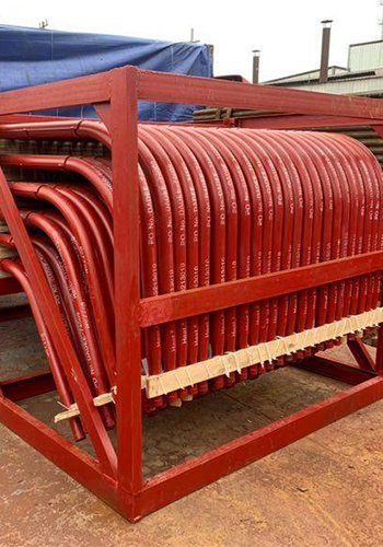
To address the operational challenges, a strategic alteration involves the elimination of the high-temperature superheater within the horizontal channel, making way for the incorporation of two distinct sections of the evaporator protector. Essential specifications of the newly integrated evaporator sections are detailed in Table 1.
Table 1 Main parameters of the new evaporator
| Pipe Diameter (mm) | Transverse Pitch(mm) | Longitudinal Pitch(mm) | Transverse rows(Rows) | Longitudinal rows(Rows) | Calculated area (m2) |
| Φ51×5/7 | 200 | 120 | 36 | 16 | 614 |
(2) Modification of Lower Inlet Piping for the New Evaporator Protector:
The integration of the new dual-section evaporator protector necessitates the introduction of two lower inlet pipes through the water-cooled wall of the horizontal channel. A dedicated conduit is established within the downpipe, serving as the outlet for the second section of the evaporator protector. This downpipe interconnects with the lower inlet pipe of the evaporator protector. The upper end of the newly introduced upflow pipe merges with the preexisting upflow pipe, ensuring a seamless flow continuum.
(3) Enhanced Design of New Evaporator Protector:
To optimize functionality, the spacing between the lower small collector boxes of the new evaporator protector is extended to 300mm, while the pitch between adjacent pipe screens is adjusted to 120mm. This meticulous configuration aims to prevent the formation of ash accumulation bridges within the new evaporator. Both upper and lower small collector boxes of the evaporator adhere to Φ108×10 specifications, constructed from 20g material.
(4) Strengthened Design for Enhanced Durability:
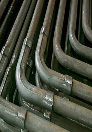
Considering the challenging environment encountered by the evaporator’s anti-friction tiles, their susceptibility to wear necessitates reinforcement. Consequently, the rows of tubes in both the front and rear sections of the evaporator are composed of robust, thick-walled tubes (7mm). Furthermore, the integration of the new evaporator entails the installation of supplementary brackets atop the furnace to ensure adequate structural support.
2.3 Remodeling of Superheaters:
The original configuration of the two-stage desuperheater is reconfigured, wherein the middle-temperature superheater is repositioned between the two sections, and the middle-temperature superheater is converted to a high-temperature superheater within the second section. This adjustment involves the incorporation of two collectors between the original two sets of medium-temperature superheaters: one functions as the outlet collector for the medium-temperature superheater, while the other serves as the modified outlet collector for the high-temperature superheater. The preexisting outlet collector for the medium superheater is repurposed as the inlet collector for the high superheater. Notably, the specification for the medium-temperature superheater outlet collector is enhanced to Φ273×16, utilizing material 12Cr1MoVG. Similarly, the specification for the high-temperature superheater outlet collector is also augmented to Φ273×16, employing material 12Cr1MoVG. Additionally, the second-stage desuperheater’s material is optimized to 12Cr1MoVG. The integration of new collectors necessitates the addition of supportive brackets atop the furnace structure.

Through revised piping configuration, the inlet of the original two-stage desuperheater is connected to the outlet collector box of the new medium-temperature superheater, while the outlet is redirected to the inlet collector box of the high-temperature superheater. The retrofit initiative encompasses the high-temperature superheater (originally the two sections of the medium-temperature superheater). To mitigate ash accumulation, the lateral pitch between tube rows in the original MTS2 section is expanded from 150mm to 180mm. Additionally, the tube screen structure is reconfigured to a 3-row design, considering steam-side resistance control.
For protection, both the preceding and succeeding tube bundles of the high-temperature superheater are outfitted with 316L anti-friction tiles, each with a thickness of 3mm. These measures are implemented to enhance durability and operational efficiency.
2.4 Rehabilitation Results:
Following the aforementioned modifications, the aggregate heating area of the boiler now stands at 11,091 m². Within this total, the superheater area encompasses 4,348 m², representing approximately 39% of the total heating area. By augmenting the convective evaporation boiler heating surface ahead of the superheater, a substantial reduction in the flue gas temperature entering the superheater is achieved. This reduction is pivotal in circumventing unfavorable operating conditions for the superheater. Simultaneously, the overall superheater area is diminished, leading to a significant reduction in the requisite volume of desuperheating water injection. This refinement assures the precise regulation of vapor-side temperatures within the superheater during both rated and overloaded operational scenarios, mitigating the risk of over-temperature occurrences. Consequently, the boiler’s operational safety and long-term stability are markedly improved, underpinned by its reliance on evaporation capacity.
The transformation’s impact is reflected in the revised thermal calculations (under rated conditions), as outlined in Table 2.
Table 2 Thermal calculation summary table (after the transformation of the evaporation rate of 90.8t / h when the parameters)
| Item | Combustion chamber | Radiant Passage | Evaporator 1 | Evaporator 2 | High over | Medium Over | Low over | Economizer |
| Flue gas inlet temperature (℃) | – | 1090 | 750 | 671 | 600 | 545 | 461 | 320 |
| Flue gas outlet temperature (℃) | 1090 | 750 | 671 | 600 | 545 | 461 | 320 | 225 |
| Theoretical flue gas volume (Nm3/h) | 162000 | 162000 | 162000 | 162000 | 162000 | 162000 | 162000 | 162000 |
| Work quality inlet temperature (℃) | 264 | 264 | 264 | 264 | 386 | 320 | 264 | 130 |
| Work quality outlet temperature (℃) | 264 | 264 | 264 | 264 | 450 | 406 | 393 | 191 |
| Heated area (㎡) | 391 | 1169 | 518 | 614 | 480 | 776 | 3092 | 3538 |
Analysis of Reform Effects:
Figure 1 displays the DCS interface following a continuous operational period of 5 months:
Extended Operational Duration and Sustained Evaporation Capacity:
The modified boiler demonstrates a marked increase in operational endurance, reliably achieving the rated evaporation capacity over extended periods.
Enhanced Superheater Inlet Flue Temperature Control:
Under rated boiler conditions, the superheater’s inlet flue temperature is notably improved, registering at 550°C post-modification, a significant reduction from the original temperature of nearly 650°C.
Substantial Reduction in Desuperheating Water Consumption:
One of the most notable improvements is the significant decrease in desuperheating water usage. Prior to the overhaul, the first-stage desuperheating water consumption stood at 11.3t/h, and the second-stage at 2.9t/h. Post-transformation, these figures are significantly lowered to 6.2t/h and 2t/h respectively.
Ash Accumulation and Soot Blower Efficacy:
Despite the improvements made, the collection box beneath the original evaporation screen still experienced residual ash accumulation, with the effectiveness of soot blowers being limited in certain areas. The accumulation issue within the middle section arises from the original design’s longitudinal pitch and minimal height difference between neighboring collector boxes. A comprehensive solution necessitates a re-evaluation and renovation of the evaporator’s horizontal arrangement.
Economic Advantages:
The economic benefits of the transformation are evident. The enhanced evaporation capacity post-modification translates to an approximate increase of 8t/h compared to the original average. Extrapolating this over an annual operating cycle of 8000 hours, with a turbine steam consumption of approximately 5kg/kWh, yields an additional annual electricity production of over 12.8 million kWh. Based on an estimated electricity rate of 0.5 yuan/kWh, this results in a revenue increase of around 6.4 million yuan per year. With a transformation cost of approximately 4 million yuan, the investment can be recouped in less than a year.

Conclusion:
The undertaken transformation of the furnace boiler heating surface has yielded significant and multi-faceted benefits. This endeavor not only boasts noteworthy economic gains but also enhances operational conditions, curbs high-temperature corrosion, and prolongs the equipment’s operational lifespan, thus warranting widespread adoption. To ensure a comprehensive and successful primary boiler heating surface modification, the following five key aspects should be diligently addressed:
Thorough Problem Identification and Feasibility Analysis:
The initial step involves a comprehensive evaluation of equipment, operational conditions, and the operating environment. Identifying existing issues and defining transformation objectives are crucial. A meticulous feasibility analysis, coupled with economic considerations, guides the decision-making process.
Detailed Project Planning and Anticipating Challenges:
Prudent project planning is paramount. Foreseeable challenges should be anticipated, and effective countermeasures devised. A comprehensive evaluation of resources including personnel, machinery, materials, methods, and the environment is essential, preparing for any contingencies.
Systematic Implementation and Resource Mobilization:
The implementation plan should be executed methodically, with the aim of fully mobilizing and harmonizing all available resources. Ensuring the secure, high-quality, and efficient accomplishment of established tasks is a priority.
Thorough Assessment and Continuous Improvement:
Upon completion, a comprehensive assessment of the transformation’s effects is necessary. A meticulous review should encompass the entire process – from initial preparation through implementation to post-transformation operations. This analysis distinguishes successes from shortcomings, correctness from missteps, and outlines areas for further refinement.
Knowledge Sharing and Ongoing Enhancement:
The successes garnered from the transformation warrant affirmation and are poised for standardization and broader promotion. The lessons learned from any failures should be comprehensively documented and analyzed. Unresolved issues should inform future transformations, driving ongoing improvement.
In embracing these five principles, a holistic and well-structured approach to boiler heating surface modification can be effectively executed, yielding sustainable and impactful results.
[Source] Wen zhifeng, Discussion on the application of boiler heating surface reconstruction of waste incinerator, ECOLOGICAL ENVIRONMENT,2023:87-91
Frequently Asked Questions (FAQs) – Boiler Heating Surface
- What is a boiler heating surface?
A boiler heating surface refers to the area where heat is exchanged between the combustion gases and water in a boiler, crucial for efficient energy transfer. - Why is the boiler heating surface important?
It plays a vital role in optimizing heat transfer, ensuring efficient combustion, and maintaining operational performance. - What is boiler heating surface reconstruction?
Boiler heating surface reconstruction involves strategic modifications to enhance efficiency, durability, and overall performance of boilers. - How does reconstruction impact boiler efficiency?
Reconstruction can improve heat transfer, reduce energy waste, and boost overall boiler efficiency. - Can boiler heating surface reconstruction extend equipment life?
Yes, by mitigating corrosion, improving operational conditions, and optimizing heat transfer, equipment life can be extended. - How does reconstruction affect energy consumption?
Efficient heating surface reconstruction can lead to reduced energy consumption and lower operating costs. - What are the key benefits of boiler heating surface reconstruction?
Benefits include increased efficiency, reduced maintenance costs, enhanced reliability, and potential energy savings. - Is reconstruction suitable for all types of boilers?
While the concept applies broadly, specifics may vary based on boiler type, size, and design. - What challenges might arise during reconstruction?
Challenges could include design adjustments, material considerations, and potential disruptions to operations. - How can I initiate a boiler heating surface reconstruction project?
Begin with a comprehensive analysis of your system’s needs, followed by a well-planned project execution in collaboration with experts.