In recent years, the widespread adoption of circulating fluidized bed (CFB) boilers in China is attributed to their high combustion efficiency, broad load adjustment range, fuel coal adaptability, and environmental friendliness. Nevertheless, the inherent process characteristics of CFB boilers lead to significant wear and tear on the furnace’s heating surface, thereby posing a substantial challenge to achieving prolonged, stable, safe, efficient, and superior boiler operation.
CNOOC Huahu Coal Chemical Co., Ltd. employs three SG-170/9.81-M2801 type CFB boilers, utilizing fluidized combustion and sectional air supply methods. Primary air is introduced into the furnace through the water-cooled air chamber at the base of the furnace via an air distribution plate, while secondary air is directed into the transition and suspension sections of the furnace through secondary air outlets. Under optimal coal conditions, the boiler consumes 27.127 t/h of coal to reach its rated load, with the designed coal particle size spanning from 0 to 12 mm (comprising 40% below 1 mm, 70% below 3 mm, 85% below 8 mm, 90% below 10 mm, and 99% below 12 mm).
1. Causes of Water Wall Wear
1.1 Impact of Coal Particle Size
The size of incoming coal particles plays a crucial role in the wear and tear of water walls. When larger coal particles are introduced into the boiler, more primary air is required to maintain optimal fluidization of the bed material. Consequently, this results in increased flue gas flow rates, which, in turn, contribute to water wall abrasion. The extent of water wall wear is directly associated with the size of the bed material particles. For wear to occur, the moving particles must possess sufficient kinetic energy. When particles are small, their kinetic energy is limited, causing minimal abrasion upon contact with the water wall. Such abrasion remains below the threshold of the pipe’s elastic deformation capabilities and poses no threat to the heating surface.
However, as coal particle size increases, so does the kinetic energy of these particles, leading to more pronounced water wall abrasion. If these oversized coal particles consist of high-carbon-content coal, their combustion within the furnace takes considerably longer compared to smaller-sized coal particles. This extended residence time exacerbates the wear on heating surfaces. Over time, the proportion of larger particles in the furnace increases, creating more significant gaps between particles. As these larger particles accumulate, they reduce the primary wind resistance, causing an abnormal “ditch flow” phenomenon. To maintain ideal fluidization throughout the bed, it becomes necessary to increase the total wind volume into the furnace, consequently intensifying material scouring of the heating surface and wear.

Figure 1 and Figure 2 illustrate the relationship between coal particle size and the primary and secondary air volume ratio entering the furnace. During actual operation, it is observed that the primary air volume exceeds the design value, while the secondary air volume falls below the design value. Additionally, the coal particle size entering the furnace is consistently greater than the intended 0-12 mm range. Although the coal particle size exceeding the standard represents a small fraction of the incoming coal, insufficient primary fluidization results in inadequate primary air volume. As a result, the bed material faces difficulties in discharging through the slagging system, necessitating an increase in primary air volume to maintain optimal fluidization. To control flue gas residual oxygen within factory specifications, the secondary air volume is consequently reduced, leading to an imbalance in the secondary air ratio.
The secondary air not only requires speed but also stiffness to ensure adequate penetration and create a robust counterflow air pattern in the combustion chamber’s dense-phase region. This configuration hinders the upward movement of material, ensuring thorough coal combustion in the furnace’s dense-phase area. The reduction of secondary air disturbs this balance, shifting combustion to the dilute-phase region and intensifying material concentration in the upper furnace, further exacerbating the aerodynamic field in the furnace and intensifying water wall wear in the upper region.
In summary, the size of coal particles entering the CFB boiler has a profound impact on water wall abrasion. The relationship between coal particle size and air volume, along with the subsequent effects on combustion, fluidization, and wear, necessitates careful consideration and adjustment to ensure the long-term, efficient, and safe operation of CFB boilers. Proper measures should be taken to address this issue and minimize water wall abrasion.
1.2 Impact of Flue Gas Flow Rate on Water Wall Wear
Flue gas flow rate is a significant factor contributing to water wall wear in CFB boilers. The higher the flue gas flow rate, the more pronounced the water wall wear becomes. Studies have revealed a third-power proportionality between wear and flue gas flow rate. Furthermore, the relationship between the flue gas flow rate, boiler load, primary and secondary air volume ratios is critical, as a greater primary and secondary air volume leads to heightened combustion conditions’ disruption within the furnace, resulting in more substantial water wall wear.
The wear rate and its correlation with flue gas flow rate and particle diameter can be expressed as follows: δ = k × u3 × d3, where δ represents the wear rate, u signifies the solid particle velocity in the flue gas, d represents the particle diameter, and k denotes a constant. When the velocity of solid particles in the flue gas remains constant, the relationship between wear rate and particle diameter is illustrated in Table 1, while in the case of constant particle diameter in the flue gas, the relationship between wear rate and particle velocity is demonstrated in Table 2.
Table 1: Relationship Between Wear Rate and Particle Diameter

Table 2: Relationship Between Wear Rate and Particle Velocity

The data in Table 1 and Table 2 reveal that a one-fold increase in particle velocity and diameter corresponds to a 32-fold increase in water wall wear rate, significantly intensifying water wall abrasion. Consequently, to mitigate water wall wear, it is imperative to control coal size, rationally adjust the primary and secondary air ratios, and regulate the air supply and induced air to maintain the excess air coefficient within the designated range, ensuring effective wear reduction on the water wall.
1.3 Composition of Fly Ash Particles
One of the distinct advantages of circulating fluidized bed boilers is their adaptability to a wide range of coal types. For energy-saving purposes, low-calorific-value, high-gangue-content, and low-quality coal is often selected for these units. Additionally, limestone powder is mixed into the fuel for desulfurization. The fly ash generated consists of various elements, including Ca, Si, Al, S, Fe, and Mg, with Ca, Fe, and Al being metal elements. Upon combustion, they form high-hardness compounds such as CaO, FeO, Al2O3, and SiO2. The increased presence of these substances in fly ash exacerbates water wall abrasion. Tests have demonstrated that bed materials with higher Si and Al components exhibit more substantial wear on the water wall.
Table 3: Hardness of Key Particles in Fly Ash
| Material | Limestone | Silicate | Aluminum oxide | Steel | Plating | Oxide film |
| Hardness Value | 140~160 | 800 | 800~900 | 130~250 | 500~1800 | 600~1800 |
1.4 Impact of Anti-Friction Processes
The anti-wear processes in fluidized bed boilers encompass both casting material anti-wear and metal spraying anti-wear techniques. The precise selection of wear-resistant material composition and the quality of construction are crucial. Inaccurate material selection and subpar construction quality can undermine the effectiveness of water wall protection.
2. Boiler Operation and Wear on Heating Surface Components
Based on the practical operational scenario, the key components experiencing wear in fluidized bed boilers are primarily concentrated in three areas:
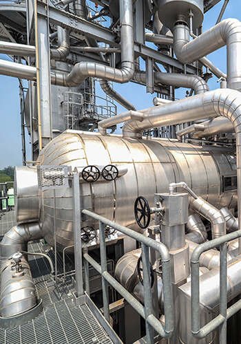
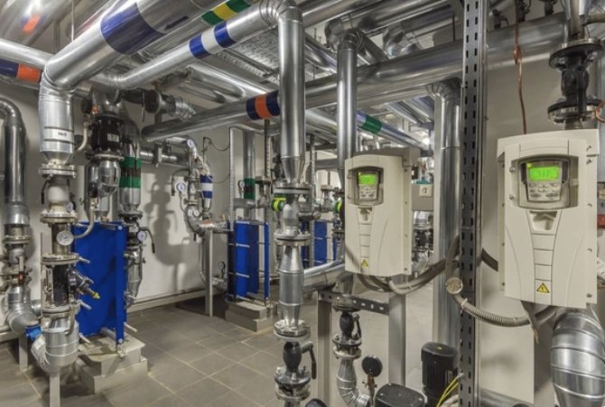
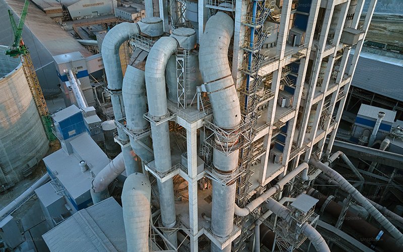
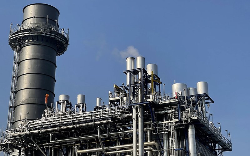
2.1. Inlet Section Beneath the Coal Pipe into the Furnace
This area is particularly susceptible to wear and tear, mainly due to the high-velocity flow of coal particles, as well as their impact and abrasion upon entry into the furnace. The continuous exposure of this region to coal particles leads to notable wear.
2.2. Water Wall Sections in the Dense Phase Area
Within the dense phase area of the boiler, water wall surfaces are exposed to a barrage of high-velocity coal particles, which significantly contribute to the wear and abrasion in this region.
2.3. Transition Zone of the Water Wall in the Combustion Belt
In the transition zone, where combustion occurs, the water wall is subjected to significant heat and thermal stress. This area is prone to wear, particularly in the vicinity of the combustion belt.
2.4. Surroundings of the Slag Cold Machine Inlet and Casting Material
The areas around the slag cold machine inlet and casting material experience wear as a result of the dynamic conditions and abrasive particles present in this part of the boiler.
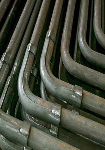
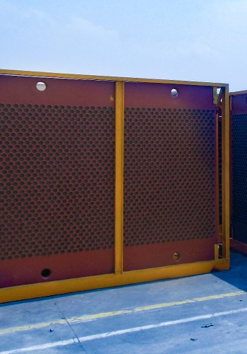
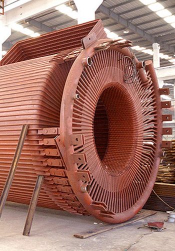
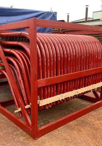
[Refer to Figure 3 to Figure 6 for Visual Representation of These Wear Locations]
These wear-prone components demand vigilant monitoring and strategic protective measures to ensure the efficient, long-term, and safe operation of fluidized bed boilers.
3. Anti-Wear Measures
Efficient mitigation of wear in fluidized bed boilers is essential for their long-term and reliable operation. Here are several key anti-wear measures that can be implemented:
3.1. Strict Control of Coal Particle Size Entering the Furnace
The size of coal particles entering the furnace is a significant contributor to water wall wear. It is essential to meticulously manage coal particle size as it impacts the overall wear rate, combustion quality, and boiler efficiency. Recommendations for controlling coal particle size include:
(1) Installation of Additional Screens: To screen out particles larger than 12 mm, a screen can be added to the lower section of the existing ring hammer crusher. These larger particles can be directed back to the ground bucket for secondary crushing.
(2) Enhanced Iron Removal Equipment: After furnace shutdown, the bed material cleanup process often reveals larger iron objects. These iron pieces can obstruct the magnetic roller gap support, allowing sizable coal particles to enter the raw coal bin. Improving iron removal procedures can help reduce wear.
(3) Reasonable Mixing of Fine Furnace Slag: In the short term, if controlling coal particle size proves challenging, incorporating a certain percentage of fine furnace slag can help fill gaps between larger particles. This promotes more even air distribution, maintains good fluidization of the bed material, and reduces the occurrence of abnormal “ditch flow” that contributes to wear. Additionally, slag contains incompletely burned carbon particles, which can reduce heat loss during combustion.

3.2. Rational Control of Primary and Secondary Air Proportions
Adapt the primary and secondary air volumes based on coal quality, boiler load, and operational conditions. Reducing the primary air volume can notably lower the flue gas flow rate, while increasing the secondary air volume enhances penetration and rigidity, effectively inhibiting the upward movement of fly ash particles and reducing wear on the furnace’s heating surface.
3.3. Control of Fly Ash Particle Composition
(1) Stringent Control of Coal Quality: The wide adaptability of circulating fluidized bed boilers to varying coal qualities allows for customized designs to meet user requirements. When designing and operating a boiler, the coal quality used should align with design specifications to achieve rated output. Significant deviations in coal quality necessitate increased coal consumption, which, in turn, leads to a cascade of deteriorating effects on boiler longevity.
(2) Reasonable Limestone Usage: Limestone with a hardness of 130~250 HV, when used in spray layers, can sequentially degrade the oxidation layer and pose a threat to the heating surface. Therefore, limestone usage should be adjusted in line with flue gas environmental protection standards to reduce limestone content in fly ash and production costs.
3.4. Stringent Quality Control in Anti-Wear Construction
(1) Adherence to Spraying Technology Requirements: Arc spraying is the current technology for surface protection. It involves the use of two self-consuming electrodes made from metal wires to generate an electric arc, which melts the wire and atomizes it with compressed air for even application on the heated surface. Before spraying, the heated surface must be thoroughly cleaned, and the spraying process should be uniform. An excessively thin or uneven coating can reduce the protective effect.
Heightened Spraying: Based on the current coal particle size entering the furnace and the heating surface wear conditions, consider raising the original design height of the dense-phase area spraying by 1 meter to improve protective effectiveness.
(2) Addition of Protective Plates or Sleeves: For areas prone to wear, such as the slag mouth and the lower coal pipe into the furnace section, adding protective plates to the lower slag mouth and wear-resistant sleeves to the lower coal pipe can effectively buffer the scouring of the water wall by material. This modification has demonstrated positive results in terms of wear protection.
Implementing these anti-wear measures ensures the enhanced durability and optimal performance of fluidized bed boilers.
4. Conclusion
Through practical operational experience and maintenance processes, this study has examined wear in circulating fluidized bed (CFB) boilers from three primary angles: the analysis of wear causes, the identification of wear-prone components, and the implementation of anti-wear measures. In particular, we have emphasized the critical impact of coal particle size on heating surface wear.
The combustion conditions in fluidized bed boiler furnaces are intricate, and the subject of heating surface wear is multifaceted. To reduce wear on the heating surface, extend operational lifecycles, and fully harness the energy-efficient and high-performance benefits of CFB boilers, future research should continue to explore this direction.
Efforts in this area will contribute to the long-term sustainability and effectiveness of circulating fluidized bed boilers in meeting energy and environmental demands.