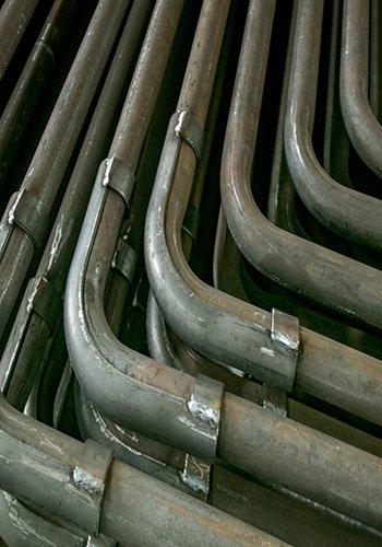
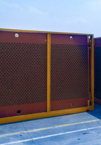
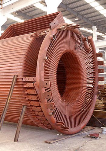
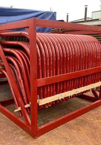
In the past decade, the implementation of low-temperature economizers downstream of air preheaters in coal-fired power plant boilers has gained significant traction as an effective energy-saving solution. This equipment aims to decrease the flue gas temperature from approximately 120 ℃ to 150 ℃ down to around 90 ℃. By doing so, it achieves a reduction in the specific resistance value of dust within the flue gas, thereby enhancing the efficiency of the electric precipitator’s dust removal process. Additionally, this system operates in synergy to eliminate pollutants such as SO3, Hg, and other contaminants present in the flue gas. Furthermore, the low-temperature boiler economizer facilitates the recovery of waste heat from the flue gas, resulting in a substantial reduction in coal consumption for the unit.
The current design of the Low-temperature Boiler Economizer primarily comprises a shell and tube finned tube structure, with the flue gas passing through the shell side and cooling water circulating through the tube side. However, its practical implementation over the past decade has brought to light two significant issues:
- Premature Wear and Tear: One prominent problem lies in the core heat exchanger tube bundle and fins—the main components of the Low-temperature Boiler Economizer. Due to the high concentration of dust in the environment, the heat exchanger elements are continuously subjected to abrasion from the dust collected before the dust collector. Despite the adoption of various enhanced anti-wear measures, the wear and tear of the heat exchanger elements remain unavoidable. Consequently, the lifespan of the heat exchanger elements is considerably reduced, and a definitive solution to this wear and tear problem is yet to be found.
- Leakage and Clogging: The Low-temperature Boiler Economizer employs a shell and tube configuration where cooling water flows through interconnected tubes. The cooling water system is commonly an open circulation system. Consequently, in the event of tube damage resulting from wear and tear, a substantial amount of cooling water continuously leaks into the flue gas. This leakage leads to the accumulation of ash, causing blockages within the Low-temperature Boiler Economizer. Such clogging significantly hinders the unit’s safe and efficient operation.
Addressing these issues is crucial to ensure the optimal performance and longevity of the Low-temperature Boiler Economizer while maintaining the safe operation of the power plant.
The research has revealed that the traditional cryogenic economizer, when placed before the electric precipitator in industrial settings, tends to develop leakage issues within a relatively short cycle of 2 to 3 years. Such leaks in the low-temperature economizer’s heat exchanger tube bundle give rise to several problems:
- Ash Accumulation and Unit Operation: Leakage results in the plugging of the heat exchanger with ash, affecting the ash delivery to the electric precipitator’s ash hopper. This, in turn, jeopardizes the safe operation of the unit.
- Reduction in Efficiency: Partial or complete failure of the heat exchanger modules leads to insufficient temperature reduction, greatly reducing the coal-saving benefits. Consequently, the dust removal efficiency of the electric precipitator diminishes, leading to a decline in the performance of environmental protection equipment downstream of the precipitator. This negatively impacts the achievement of ultra-low emission standards.
- Increased Flue Gas Resistance: Leakage-related issues contribute to a rise in flue gas resistance, which subsequently leads to an increase in the power consumption of the induced draft fan. In severe cases, it may even cause the fan to stall, disrupting the overall operational efficiency.
The combination of wear and leakage problems in the traditional low-temperature economizer has severely compromised the safe operation of power plant units and escalated operation and maintenance costs. Consequently, it has become a significant concern for users and has significantly limited its widespread application. Therefore, there is an urgent necessity for the development of a cryogenic economizer technology capable of achieving zero leakage of cooling water in the flue gas system. By addressing these issues, such a technology would enhance operational reliability, reduce maintenance costs, and provide greater convenience to users, thereby facilitating its broader implementation in power plants and industrial settings.
Technical principle
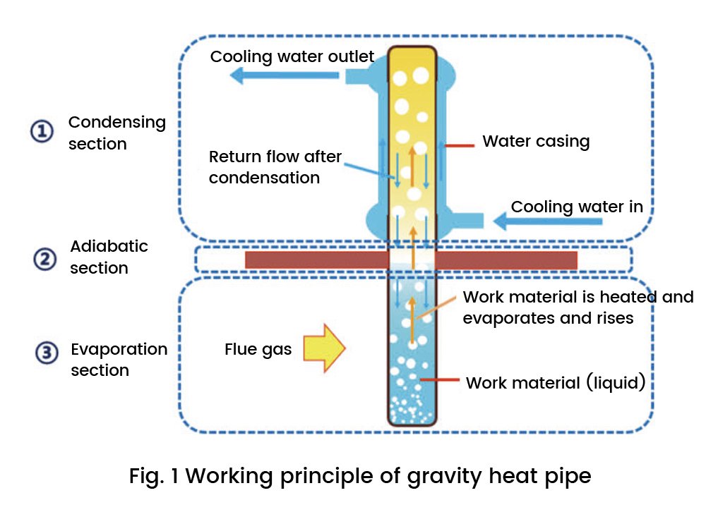
The Heat Pipe Low-temperature Boiler Economizer is an improvement upon the traditional shell and tube Low-temperature Boiler Economizer, utilizing gravity heat pipes as the heat exchange elements. These gravity heat pipes are engineered components known for their exceptional heat transfer performance. Typically, a gravity heat pipe consists of a shell, steam cavity, working medium, and is divided into three parts based on functionality: the evaporation section, adiabatic section, and condensing section (refer to Figure 1).
The technology of gravity heat pipes operates on three fundamental physics principles:
- Reduced Boiling Point in Vacuum: When the heat pipe operates in a vacuum state, the boiling point of the liquid inside it decreases.
- Latent Heat of Vaporization: The latent heat of vaporization of the working medium is significantly higher than the apparent heat of evaporation and condensation. This enables a much greater transfer of heat through the exothermic process.
- Gravity-driven Liquid Reflux: The heat pipe leverages gravity to facilitate the condensed liquid’s movement, causing it to flow back to the evaporation section to absorb heat once again.
The working principle of the gravity heat pipe is depicted in Figure 1, and it involves the following key processes:
- Heat Absorption in Evaporation Section: In the evaporation section, the tube wall absorbs heat from an external source, such as the hot flue gas, and transfers this heat to the working medium inside the tube.
- Phase Change in Evaporation Section: The working medium in the evaporation section undergoes a phase change, transitioning from a liquid to a vapor state as it absorbs heat.
- Heat Release in Condensing Section: The vaporized working medium rises to the condensing section, where it undergoes a phase change back to a liquid state, releasing heat in the process. This heat is then transferred through the tube wall to a colder medium.
- Gravity-driven Reflux: After condensation, the liquid working medium, under the influence of gravity, flows back to the evaporation section to repeat the cycle of absorbing heat, thereby achieving efficient heat transfer.
By employing gravity heat pipes, the Heat Pipe Low-temperature Boiler Economizer enhances heat exchange efficiency and addresses some of the wear and leakage issues present in traditional economizers, thus making it a promising technology for improving the performance and reliability of power plant units.
The Gravity Heat Pipe Low-temperature Boiler Economizer is a heat exchanger equipment comprising multiple gravity heat pipes. Within this system, the cooling water and flue gas flow through the upper and lower parts of the heat exchanger, respectively. The flue gas and cooling water are effectively separated by the intermediate partition and the heat pipes, ensuring that the working material inside each heat pipe is not interconnected, thereby preventing any possibility of leakage.
Each heat pipe in the gravity heat pipe low-temperature economizer functions as an independent heat exchanger element. In the event of wear and tear causing leakage in individual heat pipes, only the internal working material of the heat pipe will escape into the flue gas. This leakage is minimal, as any released working material will be vaporized by the hot flue gas, and the cooling water will remain unaffected and will not leak into the flue gas side. Consequently, the unit’s safe operation is not compromised.
Additionally, the gravity heat pipe itself possesses heat transfer adjustability. Hence, even if there is some wear loss in certain heat pipes, the overall heat transfer efficiency of the entire equipment remains relatively unaffected due to the system’s adaptability.
The design of the Gravity Heat Pipe Low-temperature Boiler Economizer allows for flexibility in adjusting the heat transfer area on both the hot and cold sides, depending on the specific flue gas parameters. This enables the control of the flue gas side’s wall temperature, ensuring that it is always maintained above the dew point temperature of water, typically above 25℃. By doing so, the equipment effectively eliminates the problem of low-temperature corrosion, contributing to improved overall performance and longevity.
Experimental studies and conclusions
To develop the Gravity Heat Pipe Low-temperature Boiler Economizer, researchers conducted heat transfer experiments based on theoretical research. The experiments aimed to study the heat transfer characteristics of heat pipe heat exchangers with various arrangements and structural forms. Figure 2 illustrates the experimental setup used in the study.
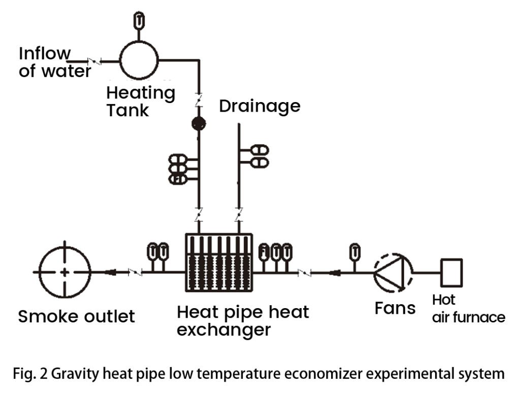
Through these heat transfer experiments; researchers investigated the performance of gravity heat pipe heat exchangers under different configurations. They studied the influence of varying arrangements and structural designs on heat transfer efficiency, thermal conductivity, and overall performance. By conducting a comprehensive analysis of the experimental data, they obtained valuable insights into the behavior and capabilities of the gravity heat pipe low-temperature economizer.
2.1 Heat transfer performance of different heat transfer structures on the flue gas side of the gravity heat pipe
The heat transfer performance of different heat transfer structures on the flue gas side of the Gravity Heat Pipe was studied through a comparison of various structural forms (refer to Figure 3). The experiments included investigating a single heat exchanger equipment with the same wind speed but different water speeds, as well as the same water speed but different wind speeds. Additionally, the heat transfer performance of a heat exchanger with the same wind speed and the same water speed conditions was compared to obtain the following conclusions:
- Comparison of Heat Transfer Coefficients: Under the same working conditions, the heat transfer coefficient of the light tube heat pipe was found to be greater than that of the finned tube heat pipe and the pinned extended surface heat pipe. This difference in heat transfer coefficients was more pronounced at different water temperatures.
- Comparison of Overall Heat Transfer Coefficients: Under the same working conditions, the overall heat transfer coefficient of the spiral finned heat pipe was found to be smaller than that of the pinned heat pipe.
- Comparison of Different Heat Pipe Shapes: The overall heat transfer coefficient of the elliptical heat pipe heat exchanger was found to be smaller than that of the round heat pipe heat exchanger.
It is important to note that although some of the above heat exchangers exhibit higher heat transfer coefficients, the practical engineering applications require considering other factors, such as heat transfer area and production processes. These factors may influence the equipment costs, which need to be taken into account during the design and selection process for the Gravity Heat Pipe Low-temperature Boiler Economizer.
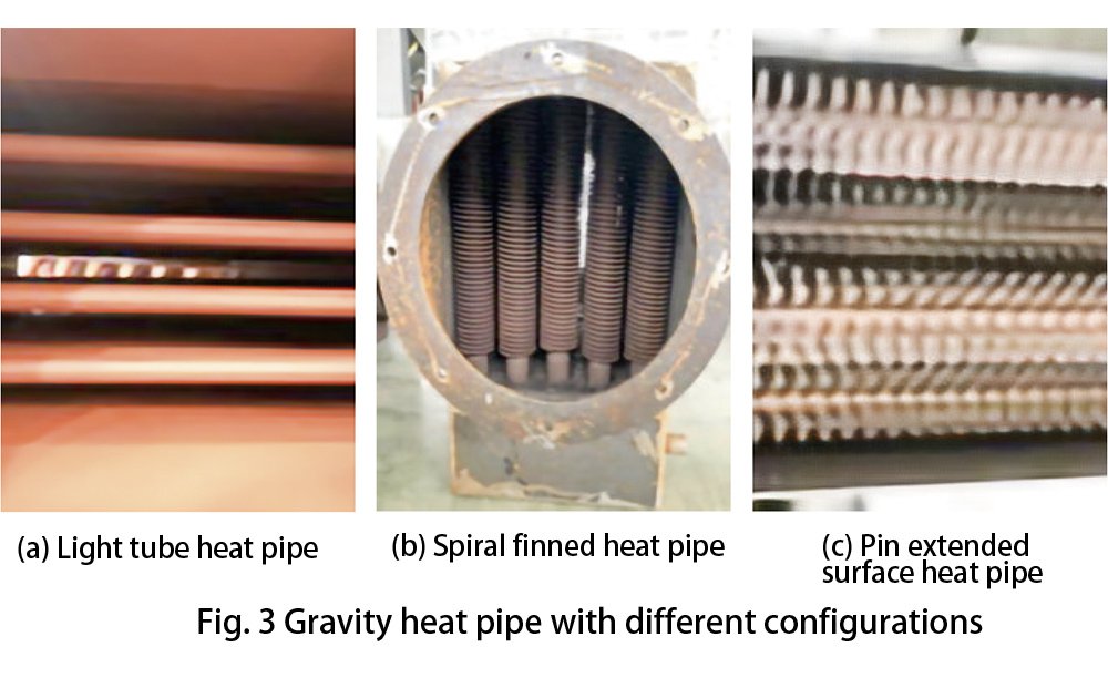
In conclusion, the study provides valuable insights into the heat transfer performance of different heat transfer structures on the flue gas side of the gravity heat pipe. This information is crucial for optimizing the design and application of the heat pipe heat exchanger, taking into account both efficiency and economic considerations in real-world engineering applications.
2.2 Research on heat transfer limit of different gravity heat pipe heat exchanger
Indeed, despite the large heat transfer capacity of heat pipes, they do have heat transfer limits that are influenced by various factors such as size and shape of the heat pipe, working medium, and temperature. In this research paper, the primary focus was on studying the impact of parameters like water temperature, smoke temperature, and heat load on the heat transfer limit of different heat pipe heat exchangers.
To determine the heat transfer limit of heat pipe heat exchangers, the study involved gradually increasing parameters such as water velocity, water temperature, flue gas temperature, and flue gas flow rate under specific working conditions. The changes in heat pipe heat transfer performance were carefully observed and recorded during these experiments.
By combining the experimental findings with the study of the heat pipe heat transfer peak, the researchers were able to refine and amend the theoretical calculation method. This improved calculation method allows for the determination of the heat transfer limit value of the heat pipe. Such a value serves as a critical guideline for selecting suitable heat pipe heat exchangers for specific applications.
Understanding the heat transfer limit of heat pipe heat exchangers is essential for optimizing their performance and ensuring their reliable operation within safe and efficient operating parameters. By investigating the effects of different parameters, this research contributes to the design and selection of heat pipe heat exchangers for various industrial and power generation applications, helping engineers make informed decisions based on specific working conditions and requirements.
2.3 Research on the amount of work material filling inside the Low-temperature Boiler Economizer of gravity heat pipe
From the working principle of gravity heat pipes, it is evident that the ideal initial liquid height within the heat pipe’s internal liquid pool is one where the work material rises up for the first time and returns to the bottom liquid pool while the material at the bottom is just about to evaporate or close to evaporation. However, in practical applications, the actual amount of liquid filling is often much larger than this ideal level. This is primarily because maintaining a certain liquid pool height allows the heat pipe to adapt to superheat flow conditions, and the liquid pool in the nucleate boiling regime can achieve a very high heat transfer coefficient. Nonetheless, excessive liquid filling can lead to various issues, including heat transfer instability and a negative impact on overall heat transfer efficiency.
To address this matter, the researchers in this study conducted theoretical analyses and repeated experiments to determine the appropriate filling volume range for the gravity heat pipe low-temperature economizer. Through their investigation, they established that the ideal filling volume range for the evaporation section of the heat pipe is within 30% to 50% of its height. The specific filling volume also varies depending on the type of heat pipe tube and the heat surface structure form employed in the heat exchanger.
By defining this optimal filling volume range, the researchers can guide the design and implementation of gravity heat pipe low-temperature economizers to ensure efficient heat transfer while avoiding potential issues associated with overfilling. This critical information will help engineers strike the right balance in heat pipe operation, achieving enhanced heat transfer performance and operational stability in real-world applications.
Innovative development of gravity heat pipe cryogenic boiler economizer
3.1 Streamlined flue gas duct design
In order to address the impact of heat pipe wear and leakage on the overall heat transfer performance of the gravity heat pipe cryogenic economizer, an essential step is to optimize the design of the flue gas duct. The wear of some heat pipes is often attributed to the non-uniformity of the gas-solid two-phase flow within the flue gas duct. To mitigate this issue and enhance heat exchanger performance, a combination of structural and flue design optimizations is needed, achieved through the application of Computational Fluid Dynamics (CFD) streamlined flue gas system design technology.
By employing CFD techniques, the internal flue design can be optimized with the incorporation of streamlined flue profiles and shaped deflector modules. This design approach effectively eliminates eddy currents and backflow of flue gases, leading to a more uniform distribution of flue gas flow into the heat exchanger. As a result, the wear on heat pipes is alleviated, and the flow field for high-efficiency heat exchange is optimized.
Additionally, the optimized flue design also yields other benefits. Firstly, it significantly reduces energy loss, resulting in improved overall energy efficiency. Secondly, the streamlined flue gas duct reduces flue gas resistance, enhancing the system’s overall performance.
By combining the advantages of the gravity heat pipe cryogenic boiler economizer with a well-optimized flue gas duct design, power plants and industrial facilities can achieve better heat transfer efficiency, extended equipment lifespan, and reduced maintenance costs. This integrated approach ensures the smooth operation of the heat exchanger while maximizing energy-saving benefits and promoting environmental sustainability.
3.2 New heat exchanger combination structure form
In the case of the Low-temperature Boiler Economizer positioned ahead of the dust collector, the flue gas often carries a high dust concentration ranging from 10 to 50g/m3. This high dust concentration makes it prone to deposits, especially during low-load conditions. To address this issue and prevent dust accumulation while maintaining convenient arrangement, conventional Low-temperature Boiler Economizers typically adopt horizontally arranged H-shaped finned tubes or spiral finned tubes in the horizontal flue section before the dust collector.
However, for the vacuum heat pipe Low-temperature Boiler Economizer, where the main heat transfer element is the gravity vacuum heat pipe, a vertical plumb arrangement is necessary to ensure smooth reflux of the internal working material to the bottom liquid pool of the heat pipe. In such cases, using conventional H-shaped finned tubes can lead to severe ash accumulation on the heated surface, adversely affecting the heat transfer performance of the vacuum heat pipe Low-temperature Boiler Economizer.
Through comprehensive research, it has been discovered that vacuum heat pipe heat exchangers employing light tubes, elliptical tubes, or spiral fins and pins as extension surfaces can effectively meet the requirements for preventing dust accumulation under the specified flue gas conditions. These alternative arrangements help maintain proper heat transfer efficiency and minimize the impact of dust deposits on the performance of the vacuum heat pipe Low-temperature Boiler Economizer.
The choice of the appropriate structural form of the heating surface in the vacuum heat pipe heat exchanger is crucial and should be tailored to the specific working conditions, taking into consideration factors like dust concentration, flue gas flow rate, and load conditions. By carefully selecting the optimal heat exchanger configuration, power plants and industrial facilities can achieve reliable and efficient heat transfer while mitigating the challenges posed by high dust concentrations in the flue gas.
3.3 Countercurrent tandem composite casing cooling water structure
The heat pipe Low-temperature Boiler Economizer features separate flow paths for cooling water and flue gas within the heat exchanger. The cooling water and flue gas flow in opposite directions, with their contact restricted by a tube plate. The two heat transfer media are contained within different sealing structures, and each heat pipe operates as an independent heat exchanger element. This setup contrasts with conventional boiler economizers where the heat exchanger tubes are interconnected. Due to this design, even in the event of wear or corrosion on the flue gas side of the heat pipe, only a small amount of the working medium inside the heat pipe will leak into the flue and be subsequently evaporated by the high-temperature flue gas. Importantly, the cooling water on the water side is unable to enter the flue, ensuring the integrity and safety of the cooling water system.
To accommodate the high-pressure operating environment of the cooling water, the condensing section of the heat pipe Low-temperature Boiler Economizer adopts a special round tube casing structure. As the cooling water enters the heat exchanger through the water inlet and the flue gas flows cross-countercurrent to the cooling water, high heat transfer efficiency is achieved. The casing round tube structure and the tube wall thickness are carefully selected through structural calculation to meet the requirements for withstanding high-pressure water conditions. Additionally, this design optimizes water flow rate, further enhancing the heat transfer efficiency of the condensing section.
By incorporating these design features, the heat pipe Low-temperature Boiler Economizer ensures efficient heat transfer while effectively handling the high-pressure conditions in the cooling water system. The independent heat exchanger elements and the round tube casing structure contribute to a reliable and high-performing economizer, addressing wear and corrosion concerns and enhancing overall energy-saving benefits in power plants and industrial facilities.
3.4 Innovative application of intelligent environmental protection
The thermal power generation industry is experiencing a shift towards digitalization and intelligent equipment in thermal power plants, presenting a new trend in the development of the sector. Long-term operation of power plant equipment, including cryogenic boiler economizers, may lead to gradual equipment failure. Traditional monitoring methods often lack real-time monitoring and early warning capabilities. To address this issue, advanced technologies are being employed, particularly with heat pipe cryogenic economizers, to enable early warning settings, real-time data monitoring, and analysis.
Through the integration of big data, Internet+, Internet of Things (IoT), and online monitoring and fault diagnosis technology, heat pipe cryogenic boiler economizers and other equipment can be equipped with early warning systems. Real-time and archived data can be compared and analyzed vertically and horizontally to establish intelligent models for early failure detection. These models enable the calculation of deviations between current values and preset expected values, issuing timely equipment failure warnings and pushing warning information to relevant personnel. This allows the spare parts library to be informed promptly, ensuring that required spare parts are procured in a timely manner to guarantee the normal operation of the equipment.
By performing comparative analysis of Low-temperature Boiler Economizer data and other relevant unit data, changes in each operating parameter of the process can be identified. A warning model for heat pipe wear failure can be established, and historical data can be imported into the model for computer learning. This enables the identification of characteristic values of heat pipe failure in heat exchanger modules compared to historical records. These findings can guide equipment operators to perform timely maintenance and treatment, thereby minimizing downtime and optimizing the healthy operation of power plant equipment.
In summary, the combination of digitalization, intelligent equipment, and advanced monitoring and diagnostic technologies is revolutionizing the thermal power generation industry, promoting efficient and proactive equipment maintenance, and ensuring the smooth and reliable operation of power plants.
Engineering applications
In 2014, a power plant in Jiangxi upgraded its 660MW unit’s boiler by implementing exhaust waste heat recovery and utilization, as well as dust removal efficiency improvements. To achieve these goals, the plant added four sets of conventional inter-wall heat exchanger Low-temperature Boiler Economizers. These boiler economizers were intended to lower the temperature of the exhaust smoke at the outlet of the air preheater, thus recovering waste heat from the flue gas, improving dust collector efficiency, and ensuring stable compliance with emission standards.
However, over time, the original shell and tube heat exchanger design of the Low-temperature Boiler Economizers proved to be problematic. The harsh environment of long-term dust washing caused wear and leakage in some heat exchanger tubes, resulting in condensate leakage into the flue. This led to ash plugging in the flue, and in severe cases, jeopardized the safe operation of the dust collector.
After extensive research conducted over the course of a year, the power plant ultimately decided to replace the conventional Low-temperature Boiler Economizers with vacuum heat pipe Low-temperature Boiler Economizers. This strategic change addressed several issues. The vacuum heat pipe technology satisfied the cooling requirements of the Low-temperature Boiler Economizer, ensuring the electrostatic precipitator (ESP) could operate at a low-temperature state. This in turn resulted in stable emissions and reduced environmental impact. Furthermore, the new vacuum heat pipe design eliminated the problems of economizer leakage and ash plugging, enhancing the overall reliability and efficiency of the power plant’s operations.
By making this upgrade, the power plant was able to effectively address the challenges posed by the original boiler economizers, achieving improved waste heat recovery, enhanced dust removal efficiency, and steady compliance with emission regulations. The successful implementation of the vacuum heat pipe Low-temperature Boiler Economizers significantly contributed to the power plant’s smooth and reliable operation, optimizing its performance and environmental sustainability.
4.1 Retrofit program
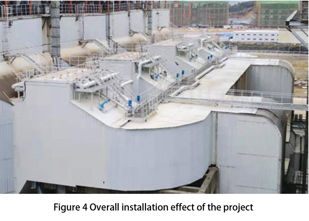
The project adopts a full-flow process route and replaces the original finned tube type Low-temperature Boiler Economizer at the inlet of the dust collector with a vacuum heat pipe Low-temperature Boiler Economizer. The layout of the new vacuum heat pipe boiler economizer is depicted in Fig. 4. The arrangement remains the same as the original Low-temperature Boiler Economizer, with placement in the four horizontal flues before the existing ESP. The overall design parameters of the heat pipe economizer are outlined in Table 1.
| Item | Unit | Value |
| Unit load | MW | 660 |
| Heat exchanger type | – | Vacuum heat pipe structure |
| Flue gas volume | m3/h | 3 700 000 |
| Medium of condensing section | – | Condensate volume |
| Condensate volume | t/h | 1480 |
| Inlet flue gas temperature | ℃ | 145 |
| Outlet flue gas temperature | ℃ | 95 |
| Flue gas side resistance | Pa | ≤ 400 |
| Water side resistance | MPa | ≤ 0.2 |
4.2 Operation effect
The heat pipe cryogenic boiler economizer of the #2 unit in this power plant began operation in December 2020, and its real-time operation data is provided in Table 2. Since the unit was put into operation during winter, and the boiler of the operating unit underwent an overhaul during this renovation, the main heat exchangers of the boiler, such as the superheater, reheater, and air preheater, were relatively cleaner, leading to high heat exchange efficiency. Consequently, the four flue gas temperatures at the air preheater exit were approximately 120°C when the unit operated at full load, which was lower than the design value.
The heat pipe Low-temperature Boiler Economizer’s outlet flue gas temperature was recorded at around 85°C, resulting in an overall temperature reduction of approximately 35°C. This significant temperature reduction demonstrates the efficient heat recovery capabilities of the heat pipe boiler economizer. Despite the lower than expected flue gas temperatures at the air preheater exit, the vacuum heat pipe Low-temperature Boiler Economizer still effectively reduces the flue gas temperature, maximizing waste heat recovery, and contributing to improved energy efficiency and environmental performance.
| Item | Unit | Value |
| Unit load | MW | 660.1 |
| Flue gas volume | m3/h | 3 496 411 |
| Inlet average smoke temperature | ℃ | 121.9 |
| Outlet average smoke temperature | ℃ | 84.5 |
| Flue gas side resistance | Pa | 362.2 |
| Water side resistance | MPa | 0.04 |
It is noted that the current cooling water volume in the heat pipe boiler economizer only accounts for 25% of the designed water volume. This indicates that there is a significant heat transfer margin in the economizer, suggesting that the heat recovery potential is not fully utilized. However, despite this margin, there are concerns about the risk of low-temperature corrosion of the heat pipe economizer and downstream equipment.
Low-temperature corrosion occurs when the flue gas temperature is too low, and it can lead to corrosion and damage to the heat exchanger and downstream components. To mitigate the risk of low-temperature corrosion, it is wise not to further reduce the outlet flue gas temperature during actual operation. By maintaining the outlet flue gas temperature at its current level, the power plant ensures the safe and reliable operation of the heat pipe boiler economizer and prevents any adverse effects on downstream equipment.
While it may be tempting to push for even lower flue gas temperatures to achieve better energy-saving effects, it is crucial to strike a balance between maximizing heat recovery and safeguarding the equipment’s integrity and performance. By operating the heat pipe boiler economizer within the designed temperature range, the power plant can still achieve significant energy savings and reduce environmental impact without compromising equipment reliability and safety.
As the power plant continues to monitor and optimize its operations, it can explore other avenues for improving energy efficiency while maintaining the long-term health and performance of its heat pipe boiler economizer and other equipment.
Conclusion
By the end of 2019, China had installed over 165 million kW of low-temperature Electrostatic Precipitators (ESPs). However, the wear and tear, leakage, and other issues associated with the Low-temperature Boiler Economizers that are compatible with these ESPs have been adversely affecting the normal and stable operation of the ESPs. This situation has hindered the achievement of ultra-low emission targets and impacted the overall economic performance of the units. Consequently, there is an urgent demand within the industry for Low-temperature Boiler Economizers that have no cooling water leakage, ensuring improved efficiency and emissions control.
Moreover, with the implementation of China’s energy-saving, emission reduction, and ultra-low emission policies, and the increasing emphasis on the “green mountains are the golden mountains” concept, there is a growing need for waste heat utilization, energy-saving, and efficiency improvements across various industries. Beyond the coal power industry, other industrial sectors will also face the challenge of flue gas treatment and the pressing need for waste heat utilization and energy-saving measures.
In this context, the heat pipe Low-temperature Boiler Economizer technology holds tremendous potential for waste heat utilization in coal-fired boilers and beyond. Its application can lead to significant energy savings, improve efficiency, and contribute to environmental protection efforts. The versatility of this technology makes it a promising solution for various industrial processes that produce waste heat, further solidifying its broad application prospects in the field of waste heat utilization.
By adopting heat pipe Low-temperature Boiler Economizers and advancing energy-efficient solutions, industries in China can align with sustainable development goals, enhance their environmental performance, and contribute to a cleaner and more sustainable future.
[Source] XIE Qing-liang, CHINA ENVIRONMENTAL PROTECTION INDUSTR: 1006-5377(2021)04-0054-05
DHB Boiler
Discover The Superior Quality And Cutting-Edge Technology Of DHB Boilers. Explore Our Range Of Biomass Boilers, Waste Heat Boilers, And More. Take Your Industrial Operations To New Heights With DHB Boiler.
