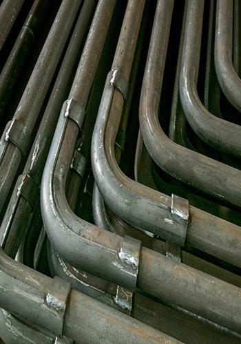
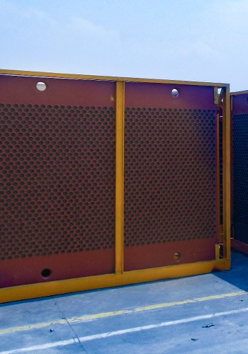
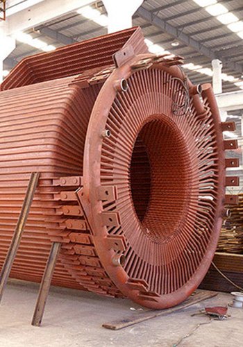
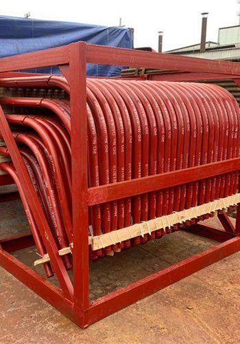
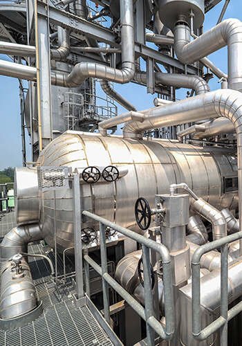
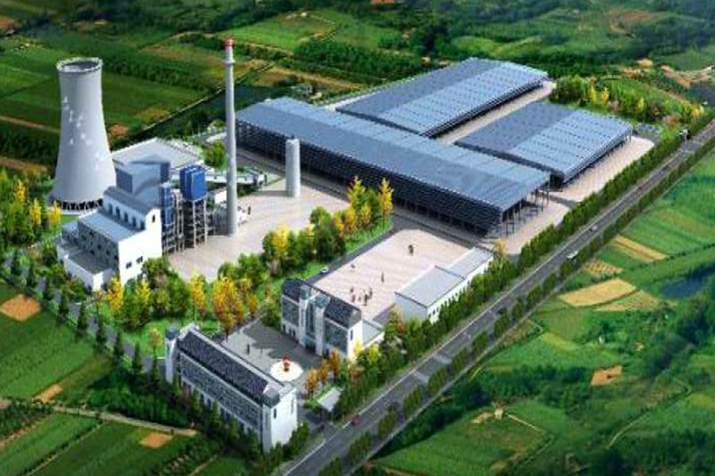
PetroChina Daqing Petrochemical’s heavy oil catalytic plant, with a capacity of 140×104 t/a, is equipped with two waste heat boilers. Each boiler is fitted with four sets of boiler economizers, comprising six sets weighing 28.1 t and two sets weighing 29.7 t. However, due to a decline in the heat exchange efficiency of the boiler economizers, all units require replacement. Additionally, the intermediate connecting flue between the boiler economizers and the expanding joints connecting the economizers to the bottom also need to be replaced.
To address these issues, a waste heat boiler economizer replacement construction process was implemented. This process involved replacing eight sets of boiler economizer modules, along with the intermediate connecting flue and two expansion joints. Remarkably, the entire replacement operation was completed within a mere eight days, resulting in a significant enhancement of the boiler economizer replacement construction efficiency.
Selection of Construction Program
The construction program selected involved the vertical arrangement of four sets of boiler economizer modules for each boiler. These modules were connected through an intermediate connection flue. The upper part of the boiler economizer modules were connected to the superheater module through expansion joints, while the bottom part was connected to the flue through expansion joints using welded connections.
The dismantling layout of the waste heat boiler economizers can be seen in Figure 1. The two waste heat boilers were situated in the center, with the pump room located on the west side and pump room 2 on the south side. The east side housed the three-stage cyclone separator, while the exhaust chimney and flue were positioned on the north side. The crane station was situated in the north side of the pipeline corridor on road 7. As the lifting operation required crossing the horizontal flue and had a significant operational radius, a 400t crawler crane was selected for the module lifting and inverted transportation based on lifting calculations.
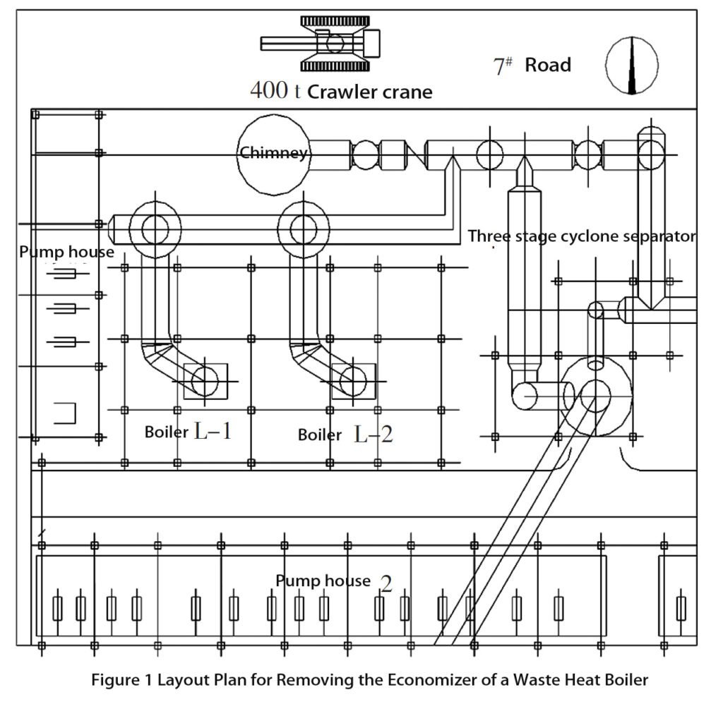
Based on the site layout, spatial structure, and measured data, three preliminary module replacement schemes were developed.
The first scheme involves removing and transporting the boiler economizer modules of the two waste heat boilers from the 6 m platform on the east side of the boiler (L-2) after dismantling. In this approach, the fixed-discharge tanks, supporting pipelines, and labor protection platforms on the platform need to be dismantled. Additionally, the instrumentation piping between the boiler economizer modules of the two boilers on the platform must be removed. This method allows the 400t crawler crane to remain in a fixed position, completing all lifting tasks without the need for the crane to move, thus reducing the associated work of repositioning the crane.
The second scheme entails transporting the modules of the east side boiler (L-2) from the east side platform and the modules of the west side boiler (L-1) from the west side platform after removing the boiler economizer modules of both boilers. Similar to the first scheme, the fixed row of tanks, supporting piping, and labor protection platform need to be dismantled. However, the west side of the boiler (L-2) has limited space for module transport, necessitating the removal of the boiler columns on the west side and implementing reinforcement measures. The lifting process requires the 400t crawler crane to move back and forth around the chimney and use additional counterweights for stability. This scheme involves a significant amount of dismantling, reinforcement, and restoration work, and the efficiency of the large crane is low, resulting in a slow speed of boiler economizer replacement.
The third scheme involves lifting the boiler economizer modules from the top of the boiler. This plan requires removing the flue gas inlet, superheater, and their supporting pipelines on the top of the boiler. Similar to the second scheme, the 400t crawler crane needs to maneuver around the chimney and employ extra counterweights. This scheme also involves a substantial workload for dismantling and restoration, and the crane’s utilization efficiency is not high.
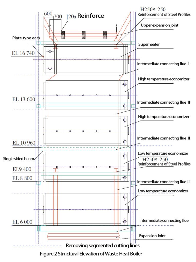
Considering the three options and taking into account factors such as construction period, workload, and cost, it was decided to adopt the first option due to its high construction efficiency. The structural elevation of the waste heat boiler is depicted in Figure [insert figure number here.
Construction Processes
2.1 Construction Process
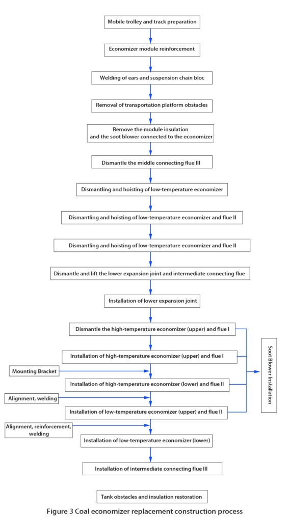
The construction flow for the replacement of the boiler economizer modules is illustrated in Figure 3.
2.2 Preparation of Moving Trolley and Track
After the boiler economizers are dismantled, transportation relies on mobile trolleys. The trolleys selected are of the 12t class specification, featuring a small self-weight, large bearing capacity, smooth and stable movement, and low traction force. For the transportation of each group of boiler economizer modules, four 12t class mobile trolleys are utilized, effectively supporting the gravity load of the boiler economizer modules.
To ensure smooth equipment transportation, a HW350×350×12×19 H-beam rail is laid underneath the mobile trolleys. ∠25×3 angles are placed on both sides of the upper flange plate of the rail, spot welded every 150 mm, and fixed onto the H-beam to prevent the mobile trolleys from derailing. Additionally, D42 mm × 3 mm short tubes are spot welded every 500 mm between the two sides of the flange plate to serve as supports. The belly plate on both sides is alternately reinforced to enhance the strength of the steel section, ensuring the safety and stability of the trolleys during module transportation on the track. The completed track is illustrated in Figure 4.
During the installation of the rail section, the connection points between two rail sections should be positioned at the steel structure platform beams. The rail is spot welded to the structure platform beams to ensure its stability. The crane pulling end is welded and securely fixed onto the steel structure.
2.3 Preparation and Reinforcement Before Module Removal
Prior to the dismantling of the boiler economizer module in the waste heat boiler, several preparatory steps and reinforcements are necessary. These include:
- Dismantling of R-3 Tank and Ancillary Piping: The R-3 tank on the east side of boiler L-2, along with its associated piping, needs to be dismantled before module removal.
- Removal of Instrument Control Box and Feeder Pipe: The instrument control box and instrument feeder pipe should be removed in preparation for the module dismantling process.
- Dismantling of Labor Protection Platform: The labor protection platform needs to be dismantled to provide access for the removal of the boiler economizer module.
- Reinforcement of Steel Structure Frame Beams: The beams in the EL 8,800 mm layer of the waste heat boiler’s steel structure frame, in the direction of the width, should be reinforced prior to module removal.
The distribution of the bearing points in the waste heat boiler is as follows:
- EL 6,000 mm Layer: The spring bearing supports the weight of the lower module of the low-temperature boiler economizer, the upper module of the low-temperature boiler economizer, and the intermediate connecting flue II and III.
- EL 13,600 mm Layer: The rigid bearing supports the weight of the lower module of the high-temperature boiler economizer, the upper module of the high-temperature boiler economizer, the superheater module, and the intermediate connecting flue I and II.
These preparations and reinforcements are crucial to ensure the safety and stability of the structure during the removal of the coal boiler economizer module.

The sequence of removing the boiler economizer modules followed a bottom-to-top approach. Each module required reinforcement and fixation to its upper module before removal. To prevent deformation and displacement of the lower flue after removing the cryogenic boiler economizer and lower expansion joints, reinforcement measures were taken.
Transverse, longitudinal, and vertical reinforcement was implemented in the transverse beams of the EL 6,000 mm layer of the boiler steel frame using 10-channel steel. This channel steel was welded to the body of the expansion joints. This reinforcement ensures stability and prevents any undesired movement or deformation.
The rail section steel was welded and securely fixed to the EL 6,000 mm layer steel structure of the waste heat boiler. Both ends of the rail section were reinforced with 14-channel steel. Additionally, two 10t plate lugs were welded to the ends of the rail sections on the side of the transport module. These plate lugs serve as attachment points for pulling the module outward during transportation. In the middle of the reinforced channel steel, a 10t class plate lug was welded, specifically designed for a fixed pulley. The 400t crawler crane utilizes the fixed pulley to pull the boiler economizer using inverted chains, facilitating the removal of the module.
These reinforcement measures and the use of pulleys ensure the safe and controlled extraction of the boiler economizer during the module removal process.
2.4 Boiler economizer removal
For the removal of the boiler economizer, the following steps were taken:
- Welding of Plate Lugs: On each side of the end face beam of the boiler steel frame at the EL 16,740 mm level, a 10t class plate lug was welded. Additionally, on each of the four corners of the dismantled boiler economizer module body frame, a 10t class plate lug was welded. The upper four lugs of the boiler economizer were suspended using inverted chains connected to the lugs on the end face beam at the EL 16,740 mm level.
- Removal of Intermediate Connecting Flue III: The intermediate connecting flue III located above the lower cryogenic boiler economizer was removed. To facilitate transportation, it was dismantled into smaller steel plates, each measuring 1,000 mm in length. After dismantling, the welds between the lower cryogenic boiler economizer and the intermediate connecting flue were cut. The lower cryogenic boiler economizer was then lifted using the inverted chain.
- Module Transportation: Track sections were inserted into the lower part of the boiler economizer module. Four mobile trolleys were placed on top of the track sections. The module was then lowered onto the trolleys using the inverted chains. The inverted chain and a 400t crawler crane were used to pull the boiler economizer module out of the boiler frame. This process was repeated for the other boiler economizer modules. The module transportation procedure is illustrated in Figure 5.
These steps ensured the safe and controlled removal of the coal boiler economizer modules from the boiler frame.
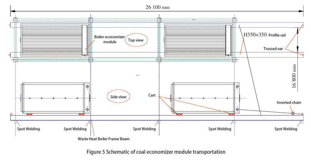
The sequence of module transportation is as follows:
- Transporting Boiler L-2 Economizer Modules: The four sets of boiler economizer modules of boiler L-2 on the east side will be transported first. These modules will be lifted and moved using the designated equipment and methods.
- Transporting Boiler L-1 Economizer Modules: After the transportation of the boiler L-2 economizer modules is completed, the four sets of boiler economizer modules of boiler L-1 on the west side will be transported. The same equipment and methods will be used to lift and transport these modules.
- Simultaneous Dismantling and Alternating Transportation: The boiler economizer modules of both boilers (L-2 and L-1) will be dismantled simultaneously. However, the transportation process will be carried out alternately, ensuring that the removal and transportation of one set of modules does not hinder the removal and transportation of the other set. This coordinated approach allows for efficient and uninterrupted progress.
By following this sequence, the transportation of the boiler economizer modules can be conducted systematically, ensuring smooth operations and minimizing any potential disruptions between the removal and transportation of the modules from each boiler.
2.5 Prefabrication of intermediate connection flues
In preparation for the installation of connecting flues, prefabrication is required for efficient on-site assembly. The following approaches were taken based on the load-bearing conditions of the equipment:
- Intermediate Connecting Flue II: The intermediate connecting flue II was prefabricated as a frame and installed in advance. This allows for smoother installation during the construction process.
- Intermediate Connecting Flue III and Intermediate Connecting Flue: These connecting flues were cut into pieces and left to be installed on-site. Their installation and welding were carried out after field measurements were taken to ensure accurate fitting.
- Intermediate Connecting Flue I: The intermediate connecting flue I was adjusted and installed based on the actual dimensions of the module on the high-temperature boiler economizer. This ensures proper alignment and fitting during installation.
The installation and welding of the intermediate connecting flue III and the intermediate connecting flue were carried out after the necessary field measurements were taken, allowing for precise installation. The installation process is illustrated in Figure 6.
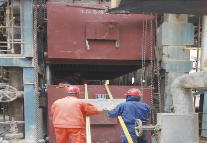
By prefabricating the intermediate connecting flues and installing them on-site according to the specific requirements and me
assortments, the construction process can be streamlined and the installation accuracy can be ensured.
2.6 Boiler economizer module installation
The installation of the boiler economizer modules follows a top-to-bottom sequence. Here is the step-by-step process:
- Module Installation: Each module is lifted and installed on the guide rail using a 400t crawler crane. The module is then slid onto the frame of the waste heat boiler using a moving trolley.
- Inverted Chain Lifting: A 10t inverted chain, installed in the frame, is used to lift the module to the desired installation elevation. Once the module reaches the correct position, it is temporarily reinforced and fixed in place.
- Removal of Inverted Chain: After the module is securely positioned, the inverted chain used for lifting is removed.
- Installation of Next Layer: Following the installation of the previous module, the next layer of the boiler economizer module is lifted and fixed in position using the same procedure.
- Lower Module Adjustment: Once all the boiler economizer modules are replaced, the lower module of the low-temperature boiler economizer is lifted by the inverted chain to create a 200 mm overhang. The guide rail steel and trolley are then withdrawn.
- Removal and Replacement of Expansion Joints: A roller bar is set up in the middle gap to remove the lower expansion joints. New expansion joints are then replaced.
- Installation of Connecting Flue: After adjusting the installation and positioning of the low-temperature boiler economizer module and expansion joints, the connecting flue is installed and welded in pieces.
The process of module installation and transportation is depicted in Figure 7, providing a visual representation of the steps involved.
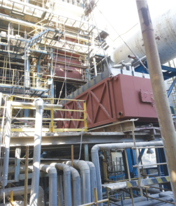
During the installation of load-bearing supports, careful attention should be given to the positioning of each support. It is crucial to consider the arrangement direction of the support long holes. The support bolts should be placed as close as possible to the outside of the long hole. This arrangement allows for the free expansion of the equipment under high-temperature conditions. By positioning the support bolts in this manner, the equipment can expand and contract without constraint.
To ensure proper support and sliding capability, stainless steel plates are placed underneath the feet of the equipment. These stainless steel plates are welded and fixed with the beam, but they are not welded to the equipment’s feet. This design allows the support to slide freely as needed.
At the interface with the old flue and superheated section, any damaged lining structures are restored using refractory alumino-silicate fibers and heat-insulating wear-resistant lining. This restoration process ensures the integrity and durability of the lining in these areas.
These measures contribute to the proper installation and functioning of the load-bearing supports, while also addressing any lining issues at specific interface points.
In conclusion, the replacement of 8 sets of boiler economizers in 2 waste heat boilers was accomplished successfully through the effective utilization of tools such as mobile trolleys, rails, cranes, pulleys, inverted chains, and their coordinated operation. The smooth completion of the replacement process, including 8 sets of boiler economizers and 2 expansion joints, within a short span of 8 days allowed for ample time for subsequent reconstruction work. This method holds valuable reference significance for similar industries involved in the replacement construction of boiler economizers and other modules in waste heat boilers.
【Source】WANG Lingqiang, MA Chunwei, LIU Yang, CHEN Xiaoyong China Petroleum first Construction Limited Corporation, Luoyang 471023, China
DHB Boiler
Discover The Superior Quality And Cutting-Edge Technology Of DHB Boilers. Explore Our Range Of Biomass Boilers, Waste Heat Boilers, And More. Take Your Industrial Operations To New Heights With DHB Boiler.
