In routine manufacturing and installation inspections, pressurized components often experience premature failures due to defects in heat treatment equipment, incorrect processes, and deviations in the overall operation. Similarly, during the initial periodic inspection of boilers, issues related to the mentioned factors have been identified in boilers that have recently been put into operation. This article analyzes the reasons for the formation of non-compliant indicators (such as metallographic structure, hardness, etc.) based on relevant cases collected in recent years. Additionally, it provides a concise overview of technical regulations and standards pertaining to heat treatment processes for pressurized components. Recommendations for practical measures are suggested to enhance the effectiveness of the heat treatment process implementation and ensure compliance with desired outcomes.
For medium and high-parameter boilers, the unavoidable use of thick-walled and various alloy materials during the design, manufacturing, and installation processes is attributed to the increased pressure and temperature requirements. Thick-walled materials and alloys pose challenges such as multiple welding layers, poor weldability, high welding process energy, and difficulties in quality testing for relatively thin-walled structures. Rigorous quality control is essential at every stage, particularly in the post-weld heat treatment phase, to guarantee safety and quality. Post-weld heat treatment aims to eliminate residual stresses introduced by welding or cold/hot working, improve the structure and performance of welded joints, reduce local stresses from cold/hot working, and prevent the occurrence of delayed cracking—a crucial step for later pressurized operation and safety assurance.
However, the author frequently observes, through inspections, that due to lax adherence to heat treatment processes and insufficient quality control, pressurized components in medium and high-parameter boilers fail prematurely (either before usage or during a short service life). This article exemplifies and analyzes cases of pressurized component failures in power plant boilers discovered during manufacturing inspections and on-site installation inspections over the years. The analysis delves into problems during the supervision and inspection of the heat treatment process, examining issues related to heat treatment equipment, processes, and deviations in inspection results from standard specifications. Targeted measures are proposed to effectively control the safety and quality of boiler header components in power plant boilers from the manufacturing and installation stages.
Inadequate Heat Treatment Leading to Component Failures: A Brief Analysis
1.1 Case 1
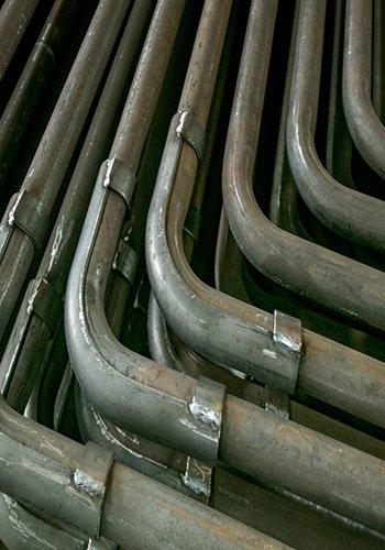
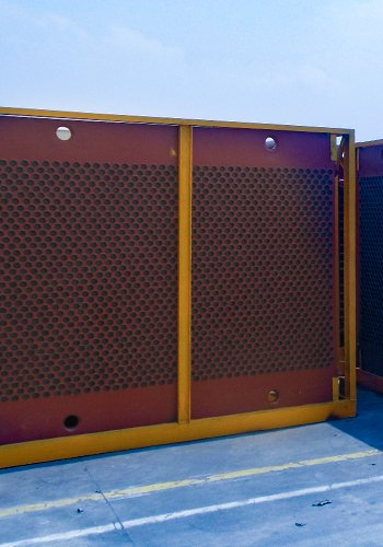
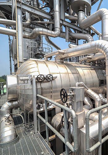
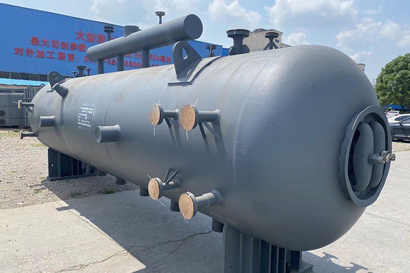
1) Situation Description: Eight screen-type superheater inlet and outlet headers (referred to as screen headers), with specifications of φ219 mm × 21 mm and made of 12Cr1MoVG, were produced by a manufacturing company. Following the completion of manufacturing, a metallographic analysis was conducted according to user requirements, based on DL/T 773—2016 “Spheroidization Grading Standard for 12Cr1MoV Steel Used in Thermal Power Plants” [1]. The results revealed anomalies in the majority of the headers, including spheroidization and hardness reduction. Specifically, two headers were graded at level 4, with hardness measurements of HB127 and HB123, and three headers were graded at level 3.5, with on-site hardness measurements of HB135, HB138, and HB140. The remaining two headers were graded at levels 2 and 3, with hardness measurements of HB172 and HB153. Seven out of eight headers exceeded the specified spheroidization level of 2.5, contrary to user requirements. Real-life photos of the headers are shown in Figures 1 and 2, and on-site metallographic analysis images are presented in Figures 3 to 8, with selected results provided in Table 1.
Table 1 Partial Analysis Results of Metallographic Structure for Screen Headers
| Location | Microstructure Image | Microstructure | Spheroidization Level |
|---|---|---|---|
| Screen Header 1-1 End 1 | Figure 3, Figure 4 | Ferrite + Carbides | Level 4 |
| Screen Header 1-1 Near Middle | Figure 5, Figure 6 | Ferrite + Pearlite | Level 3 |
| Screen Header 1-4 End 1 | Figure 7 | Ferrite + Bainite | Level 4 |
| Screen Header 1-5 End 1 | Figure 8 | Ferrite + Bainite | Level 3.5 |

2) Root Cause Analysis: The manufacturing unit, which produces A-grade boiler components, is equipped with heat treatment furnaces and localized heat treatment equipment. The heat treatment process stipulates that for components like headers, overall heat treatment is performed in the furnace after welding. For irregular tubular devices with bent pipes or multidimensional shapes, localized heat treatment equipment is used to treat the weld seams. Inspection of the equipment and processes revealed several issues (see Table 2), such as improper placement of heating devices in the furnace, absence of heating devices on the sides, and lack of thermocouples in the upper-middle section. Placing eight screen headers in the furnace as a batch led to temperature discrepancies due to overlapping, causing abnormal changes in metallographic structure. The failure to calibrate temperature-measuring thermocouples regularly resulted in temperature deviations, leading to non-compliance with material temperature limits specified in the heat treatment process card. The furnace did not undergo periodic testing for effective heating zone and temperature uniformity according to GB/T 9452—2012 “Method for Determination of Effective Heating Zone of Heat Treatment Furnace,” causing temperature gradients and non-compliance with some structure and physical indicators. Damage to the refractory insulation layer in the furnace, left unrepaired, affected the effectiveness of heat treatment. Severe spheroidization in this product resulted from issues related to the heat treatment equipment and non-adherence to the process.

Table 2 Issues Found in Heat Treatment Furnace Inspection
| Image | Photo Description | Summary of Issues |
|---|---|---|
| Figure 9 | Overall View of Heat Treatment Furnace | Absence of heating devices on sides and ends, causing significant temperature gradients in upper and lower sections when the furnace is full. |
| Figure 10 | Explanation of Electric Heating Elements Inside the Furnace | Absence of heating devices on sides and ends. |
| Figure 10 | Setting of Thermocouples Inside the Furnace | Thermocouples only installed on the bottom side, without monitoring temperatures on sides and upper parts after loading the furnace. |
1.2 Case 2
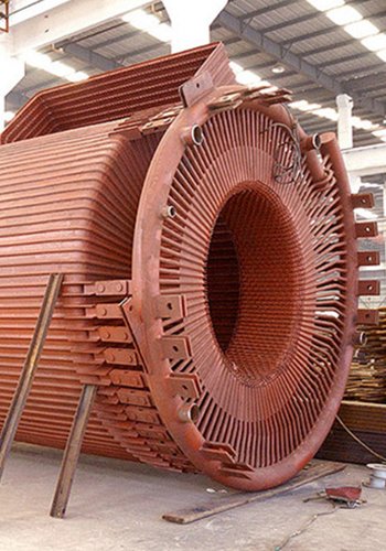
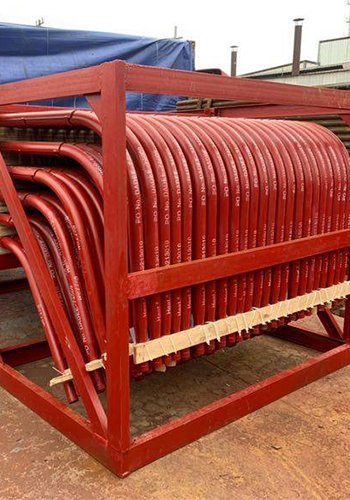
1) Situation Description: In the heat treatment process for superheater headers produced for a specific unit, incorrect temperature settings led to the external discoloration and significant peeling of oxide layers on the batch of materials. Real-life photos are shown in Figure 11, and metallographic inspections revealed coarse grains, changes in lamellar pearlite morphology, and various magnifications of metallographic structures in Figures 12 and 13.
2) Cause: Deficiencies were identified in the heat treatment process and management, including the absence of dedicated component-specific heat treatment processes. Relying solely on generic processes without specific guidelines for components can result in incorrect selection of process parameters such as constant temperature and time. Additionally, insufficient commitment from heat treatment operators played a role in the occurrence of these issues.

1.3 Case 3
During on-site inspections of the installation of a power plant boiler (rated evaporation of 220 t/h, rated working pressure and temperature of 9.8 MPa and 540 ℃, respectively), the following heat treatment issues were identified:
1) The connection weld between the screen-type superheater inlet header (made of 12Cr1MoVG) and the communication pipe to the low-temperature superheater outlet header (made of 20G, φ273 mm × 16 mm) is a dissimilar steel weld. The heat treatment process card specified constant temperature and time based on 12Cr1MoVG material, but the selection of constant temperature and time did not comply with the corresponding specifications, affecting the heat treatment results.
2) For structurally unique fittings such as three-way pipes, when local heat treatment was applied to the welds, not all parts were covered, resulting in uneven temperature distribution. During the heat treatment of tubular components, the two ends of the pipe ports were not thermally insulated, leading to significant temperature gradients on the inner and outer walls. The insulation material’s coverage width was insufficient (did not meet the standard requirement of 2 times the heating band width), and the thickness was inadequate. The insulation layer was tied with iron wire and compressed into a groove, increasing the thermal conductivity and affecting the insulation effectiveness. Due to these issues, poor heat treatment results were achieved, and additional stress was generated.
3) The main steam header made of 12Cr1MoVG material with a specification of φ325 mm × 16 mm required preheating before welding, which was not performed during actual execution. Post-weld heat treatment was not carried out immediately, and hydrogen removal (post-weld heat treatment) was not performed. The process card and the welding and heat treatment operation guide did not specify the need for post-weld heat treatment in such cases.
4) During the installation, a common issue was that the number of welds treated in the same batch exceeded the specified capacity of the heat treatment equipment, resulting in some welds not being fully monitored and recorded for temperature and other parameters throughout the process.
5) The installation period coincided with late spring and early summer, frequent thunderstorms occurred, and no relevant measures were taken for outdoor workpieces exposed to sudden weather changes, affecting the treatment effectiveness.
6) Thermocouples were all installed using a strapped method, with the thermocouples clamped between the workpiece (weld seam, etc.) and the heating device. The end of the thermocouples was directly exposed to baking, causing a positive deviation in the displayed constant temperature during heat treatment, which could not represent the actual temperature of the workpiece.
7) Some real-time heat treatment curves could not accurately reflect the actual conditions of the heat treatment equipment and process. Heat treatment personnel did not accurately and truthfully fill out heat treatment records, did not specify which weld number the curve represented, and did not conduct effective tracking throughout the entire process. The personnel responsible for heat treatment did not rigorously oversee the consistency between the process formulation and disclosure, heat treatment record reports, and curve verification with the process.
Prevention Measures Analysis
2.1 Measures Based on Heat Treatment Process Inspection
The heat treatment process in the manufacturing and on-site installation of pressure equipment is characterized by its timeliness. Before the manufacturing and on-site installation inspections leading up to the heat treatment process, it is crucial to promptly verify the formulation of heat treatment operation guides and process cards, the configuration of heat treatment personnel (responsible personnel and on-site operators), and the setup of heat treatment equipment. Instead of only reviewing heat treatment records, reports, and curves after the fact, inspections should be conducted promptly on-site during heat treatment. The on-site inspection of heat treatment equipment should include the integrity and completeness of the entire set of heat treatment equipment. Check whether thermocouples and related instruments are within the specified calibration period, with particular attention to verifying the calibration status of thermocouples. Ensure the availability of equipment for printing process curve records, and conduct a test check at the site before the heat treatment process begins. Regular on-site tracking inspections during the heat treatment process are essential. Check the number and installation compliance of thermocouples on-site, confirm whether the insulation layer thickness and bundling meet requirements, and ensure that curves are being printed and tracked normally. Use a temperature measuring instrument to determine on-site heat treatment temperatures if necessary. After heat treatment, promptly check whether relevant records and curves meet requirements. Examine the hardness determination of welds, ensuring that hardness values comply with relevant technical standards. If hardness values do not meet requirements, verify whether subsequent metallographic testing or reheat treatment procedures have been implemented.
2.2 Measures for Manufacturing and Installation Units during the Implementation of the Heat Treatment Process
Materials and specifications for medium and high-parameter boilers are diverse. The heat treatment process should comply with relevant regulations and standards. For boilers to be manufactured and installed, specific requirements for heat treatment sub-items related to the project should be stipulated and communicated to relevant personnel, starting from the quality plan and throughout the process implementation. Given the wide-ranging scope of heat treatment during on-site installation processes (involving different material specifications), corresponding ranges requiring heat treatment must be specified in accordance with the respective regulations and standards. Detailed heat treatment processes should be developed based on material categories, material specifications, and other relevant factors. Compliance with the quality system’s requirements should be ensured, and timely approval procedures should be followed. Competent individuals with proficiency, relevant professional knowledge, and on-site operational capabilities, as well as a strong sense of responsibility, should be designated as heat treatment personnel. Construction units should strengthen the management of heat treatment personnel. Due to the extended duration of heat treatment, which may sometimes be scheduled at night to avoid occupying construction power, challenges are posed to on-site management. Therefore, robust on-site duty management must be implemented. Contingency plans should be in place for electrical faults and sudden weather changes during the heat treatment process, enabling effective responses and ensuring that the heat treatment results align with regulations. The manufacturing of pressure equipment has become increasingly specialized. Components are often subcontracted, and a considerable portion of elements are handled by non-destructive testing (NDT) professional organizations, leading to varying levels of capabilities. To evaluate the quality of subcontracting, the commissioning party should conduct an assessment before subcontracting, paying special attention to verifying whether the subcontracting entity’s heat treatment capabilities, equipment status, and process capabilities comply with the requirements of relevant regulations and technical standards. The inspection unit should conduct on-site inspections and confirm the above during the assessment. For pressure equipment manufacturing units, which generally have corresponding heat treatment furnaces, regular checks should be conducted to ensure compliance with relevant regulations. Assess whether the temperature uniformity test of the effective heating zone specified in GB/T 9452—2012 is conducted regularly and whether corrective actions are taken when the test fails to meet requirements. For local heat treatment, check whether the heating band, insulation layer width, and other aspects comply with standard requirements. Verify whether the heat treatment wrapping scope of irregular-shaped fittings, such as three-way pipes and valves, meets standard requirements. Confirm if the installation positions and quantities of thermocouples comply with requirements. Ensure the real-time effectiveness of curve printing, and eliminate manual modifications of temperature, time, and other record data [2].
Conclusion
During product manufacturing inspections of a boiler component manufacturing unit, it is not uncommon to discover that improper heat treatment results in microstructures, hardness, and other physicochemical indicators of collectors and piping systems not meeting specifications or user requirements, leading to rejection. On one hand, this results in material wastage and consumes valuable time. Given the high value of materials, especially those with thick walls and alloy compositions, it causes significant economic losses for manufacturing enterprises. On the other hand, it also hampers the progress of on-site installation for users. In recent years, especially since the issuance of the “Notice on Special Inspection and Rectification of Pipeline Hazards in the Scope of Power Station Boiler” (Market Supervision Office Letter [2018] No. 515) [3], the author has identified serious spheroidization issues in some components of pipelines within the scope of power station boilers in the local jurisdiction, even in boilers that have been in operation for only a year with less than 2,000 operating hours. Similar situations have been observed during manufacturing inspections, attracting the attention of higher-level regulatory authorities. The root cause of these issues lies in deviations in the heat treatment process during the manufacturing and installation of some components. Therefore, strengthening effective inspections throughout the entire heat treatment process is an urgent priority.
References:
[1] DL/T 773—2016 Standard for Spheroidizing Rating of 12Cr1MoV Steel in Thermal Power Plants [S].
[2] Liu Hongguo. Metal Supervision and Welding [M]. Beijing: China Electric Power Press, 2017.
[3] Notice on Special Inspection and Rectification of Pipeline Hazards in the Scope of Power Station Boiler (Market Supervision Office Letter [2018] No. 515) [EB/OL]. Available at: https://www.samr.gov.cn/zw/zfxxgk/fdzdgknr/bgt/art/2023/art_962dd2dc7f504c56b8ce70891e251257.html. Accessed on January 2, 2019, to July 20, 2022.