Introduction
The tragedy of the “8.11” high-pressure steam pipeline rupture and explosion accident in Dangyang, which took place in 2016, is etched in our memories. This catastrophic event led to the loss of 22 lives, inflicted four serious injuries, and incurred a direct economic loss exceeding 20 million yuan. The steam pipelines in power plant boilers are typically characterized by their high temperature and pressure, necessitating stringent safety and reliability standards due to their substantial expansion volumes. The occurrence of such an accident can lead to profound losses and significant societal impacts.
The integrity and safety performance of a pipeline system are contingent upon several factors. These include the operating conditions, the material of the pipeline itself, and the state of stress within the system. Operating conditions are primarily shaped by the demands of the work being performed [1]. The quality of the pipeline material is influenced by the quality of its manufacturing, installation, and the conditions under which it operates [2, 3]. Meanwhile, the state of stress is largely determined by the arrangement of the pipeline and the configuration of the support and hanger devices along its length.
The failure of these supports and hangers can lead to an increase in pipeline stress, a reduction in the service life of the pipeline, and can jeopardize the safe operation of both the pipeline and associated equipment. Moreover, it heightens the risk of pipeline vibration [4-6]. Consequently, the condition of the pipelines and their support brackets is pivotal to the stress levels within the steam pipeline system and to ensuring its secure, long-term operation.
This aspect of safety is often the most neglected by installation units during the installation phase of pipelines and support brackets, as well as by operational units in their routine management and maintenance. Regardless of whether it is a newly commissioned unit or an existing one that has been in service for several years, identifying issues within the pipelines and support brackets necessitates an immediate comprehensive safety inspection of the entire steam pipeline system. Following this inspection, a safety status evaluation and stress analysis of the system should be conducted based on the findings. Subsequently, a plan for adjustment should be formulated to realign the system with its designed state or as close to it as possible.
According to the “Boiler Regulations,” both supervision and regular inspection of power plant boilers require inspection of pipelines and support brackets. However, the “Boiler Regulations” do not detail the inspection methods and key points. This paper systematically introduces the inspection methods and key points of the safety status of steam pipelines and support brackets in the power plant boiler inspection process from the aspects of data collection and review, on-site inspection and measurement, and key points of inspection at each stage. It provides an introductory guide for inspectors to carry out inspections of power plant boiler steam pipelines and support brackets, provides a reference for further developing targeted inspection plans, and also lays a solid foundation for further safety status assessment, stress calculation and analysis, and development of support bracket adjustment plans for the pipeline system. It can also provide reference for the technical management work of similar pressure pipeline design, installation, and use units.
1 Inspection Work Process
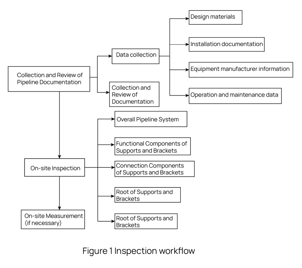
According to the requirements of relevant standards [7-9] and the summary of experience in literature [1, 10], the main work process of the safety status inspection of power plant boiler steam pipelines and support brackets includes pipeline data collection and review, on-site inspection, and on-site measurement, as shown in Figure 1.
2 Pipeline Data Collection and Review
2.1 Pipeline and Support Bracket Data Collection
The data of pipelines and support brackets mainly includes: design data, installation data, equipment manufacturer data, operation and maintenance data, etc., as follows:
2.1.1 Design Data
(1) Pipeline and support bracket design drawings (including: system flow charts, installation drawings, and design change notices).
(2) Three-dimensional drawings marking the type and position of support brackets, weld locations, pipe section sizes, and pipeline gradients (or factory piping drawings).
(3) Original data for pipeline stress calculation (including: pipeline material, specifications, unit weight, additional displacements at endpoints, calculated pressure, calculated temperature, ambient temperature, and corresponding allowable stress, elastic modulus, and linear expansion coefficient), stress calculation results table (including: cold state, hot state, hydrostatic test, accidental load, wind load or earthquake conditions stress safety judgment, endpoint force and torque table), and support bracket list (including cold and hot state displacements).
(4) Pipeline technical conditions, pipeline detail list.
2.1.2 Installation Data
(1) Records and detailed drawings of installation modifications, acceptance data at the time of construction handover.
(2) Installation data recording the location of welds and the actual installation of support brackets.
(3) The actual insulation structure and insulation material density used during installation.
(4) Pipeline welding process and welding records, as well as welding inspection records.
2.1.3 Equipment Manufacturer Data
The allowed thrust and torque provided by the equipment manufacturer at the connection between the pipeline and the equipment.
2.1.4 Operation and Maintenance Data
(1) Data on modifications, repairs, and adjustments to the pipeline system (including pipes, fittings, valves, support brackets, and various accessories) after the unit is put into operation.
(2) Data on pipeline operating parameters and fluctuations.
2.2 Data Review and Analysis
The main work of data review and analysis is as follows:
(1) Review the original design data, establish a stress analysis calculation model for the pipeline system, perform design verification, calculate the maximum stress distribution, equipment endpoint thrust and thrust torque, support bracket load and displacement value, and draw a pipeline single-line diagram for inspection use.
(2) Review the data of support brackets for each inspection, replacement, and adjustment, and other data that may affect pipeline stress, such as pipeline modifications and repairs.
(3) Review whether the actual operating parameters (temperature, pressure) of the pipeline and their fluctuations meet the design requirements.
3 On-site Inspection of Pipelines and Support Brackets
The inspection of pipelines and support brackets can promptly discover potential safety hazards and prevent the expansion of defects in pipelines and support brackets. The inspection of pipelines and support brackets is generally divided into cold-state inspections during shutdown and hot-state inspections during operation, recording the overall condition of the support brackets and the displacement in cold and hot states. The inspection mainly relies on the design data of the pipeline and support brackets. For in-service units, it is also necessary to refer to the data of the pipeline and support brackets for each inspection, replacement, adjustment, transformation, and repair. The tools used for the inspection generally include telescopes, cameras, laser rangefinders, and rulers.
3.1 Introduction to Types of Support Brackets
Pipeline support brackets can be divided into three major categories according to their functions, and each type can be further divided into several types according to their use, as shown in Table 1.
The table in the image translates to English as follows:
| No. | Classification | Type | ||
| Name | Function | Name | Purpose | |
| 1 | Load bearing support hanger | A device designed to withstand the weight of piping systems | Hengli Spring Support Hanger | Used in places where there is significant vertical displacement of pipelines or where load transfer is required |
| Variable force spring support hanger | Used in places where the vertical displacement of the pipeline is not too large | |||
| Rigid hanger | Used in places where there is no vertical displacement or where the vertical displacement is small and constraints are allowed for pipelines | |||
| Sliding bracket | Support the pipeline on a sliding support surface to constrain the vertical downward displacement of the pipeline system at the support and suspension points without restricting horizontal displacement | |||
| Rolling support hanger | Support the pipeline on rolling components to constrain the vertical downward displacement of the pipeline system at the support and suspension points without restricting axial displacement | |||
| 2 | Limit support hanger | A device designed to restrict and constrain the free displacement of piping systems caused by thermal expansion | Limit device | Not bearing the self weight load of the pipeline; Used in piping systems where displacement in one (several) directions needs to be restricted |
| Guiding device | The place where the pipeline is guided to move in a predetermined direction while restricting displacement in other directions | |||
| Fixed bracket | Used in places where pipeline displacement in any direction is not allowed | |||
| 3 | Vibration control device | Control device used to prevent pipeline swinging, vibration, or impact | Shock absorber | Used in places where continuous fluid vibration control is required |
| Damper | Used in places where it is necessary to control fluid vibrations and seismic excitations with impact | |||
Table 1: Classification and Types of Support Brackets
3.2 Inspection Content of Pipelines and Support Brackets
3.2.1 Overall Pipeline System Inspection
(1) Check whether the expansion of the pipeline system at the port is consistent with the design, and inspect the port for damage in case of abnormal expansion.
(2) Check whether the pipeline installation is consistent with the design, including the pipeline installation position and pipe length; whether the thermal expansion displacement is consistent with the design, whether the expansion is limited by adjacent buildings, equipment, or components, and the pipeline should not be obstructed by expansion except for the parts with limit devices, rigid support brackets, and fixed brackets.
(3) Check whether the pipeline has been subjected to abnormal impact loads or severe vibrations, such as causing cracking of welded joints, loosening of bolts, deformation, and damage of components; whether the pipeline insulation is intact.
(4) Check whether the installation of the support brackets is consistent with the design, including the installation position, total number, type and model of support brackets, structure of support brackets, and bias installation of support brackets; check whether the lock nut of the support brackets is tightened; check whether the load-bearing structure welds are cracked; for high-temperature steam pipelines, also check the re-inspection of alloy material of the support bracket pipe part, and conduct on-site spot checks when necessary; the deviation of the pipeline support point positioning from the design should not exceed 20 mm [7].
(5) Check for signs of deformation or deterioration of the support brackets, such as surface deformation and corrosion; whether there are external obstacles that hinder the normal displacement of the mechanism.
3.2.2 Inspection of Support Bracket Functional Components
(1) Variable force spring support brackets: Check whether the locking device is removed, whether the spring is excessively compressed, unloaded, jammed; whether the spring is biased, broken; whether the stroke is stuck; whether there is rust or other debris in the spring box.
(2) Constant force spring support brackets: Check whether the locking device is removed, whether the displacement pointer is missing; whether the displacement pointer exceeds the limit, whether there is a margin at both ends of the stroke range; whether the fixed pin interferes with the rotation of the frame.
(3) Rigid hangers, sliding supports, guide supports, fixed supports, and limit devices: The working surface should be smooth, without jamming or emptying; check whether there are cracks in the main force-bearing welds, and whether there is damage; whether the rigid hanger is normally loaded, without unloading; whether the fixed support is firmly reliable, and the bolts are loose.
(4) Dampers and shock absorbers: Check whether the oil system and stroke of the damper are normal, and whether there is oil leakage; whether the structure of the shock absorber is intact.
3.2.3 Inspection of Support Bracket Connection Components
(1) Check whether the support bracket hanger rod is twisted or bent; the angle between the rigid hanger and spring hanger hanger rod and the vertical line should not exceed 3° and 4° respectively [7].
(2) Check whether the hanger rod thread is at least 15mm above the inner end face of the flower basket nut hole [8].
3.2.4 Inspection of Support Bracket Roots
(1) Check whether the auxiliary steel structure at the root has obvious deformation; check whether the concrete structure (support pier) of the support bracket root has cracks or damage.
(2) Check whether the connected base plate matches the design.
3.2.5 Inspection of Support Bracket Piping
(1) Check whether the pipe clamps, pipe clips, or supports are correctly connected to the pipeline; whether the crossbeam is severely tilted; whether there are obvious deformations, loosening, or detachment of parts.
(2) The crossbeam of the anti-kickback rigid hanger must not be welded with the pipe support, and the hot state spacing must meet the design requirements.
(3) Check whether the piping of the sliding support, guide support, and limit device exceeds the limit; for sliding supports or guide devices with polytetrafluoroethylene (PTFE) plates, check whether the sliding base plate of the piping is covered with PTFE plates in both cold and hot states; guide devices and limit devices should not impose constraints on the pipeline that exceed the design range.
3.3 Typical Defect Examples
Typical defect examples are shown in Figures 2 to 6.
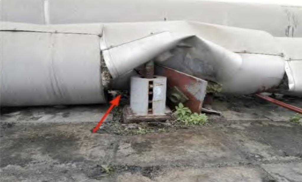
Figure 2 Pipeline displacement, spring support bracket off
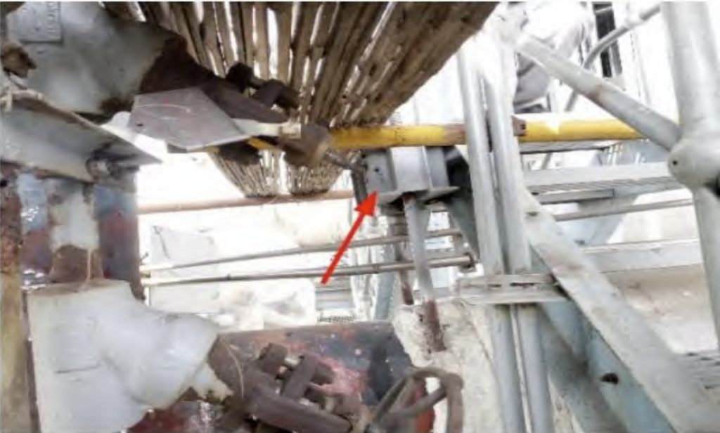
Figure 3 Pipe department and platform ladder interference
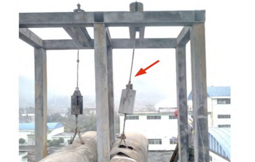
Figure 4 The inclination of the hanger rod exceeds the standard
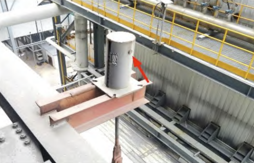
Figure 5: The pin of the variable force spring support hanger is not pulled out
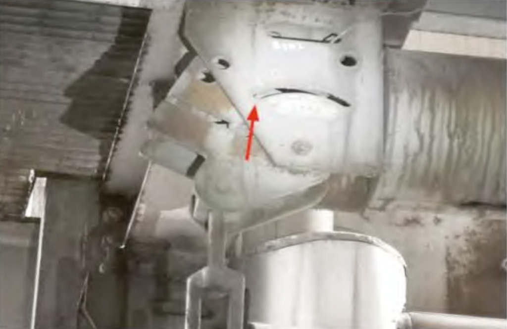
Figure 6: The pointer of the constant force spring support hanger is located at the lower limit
4 On-site Measurement of Pipelines and Support Brackets
For steam pipeline systems with abnormal pipeline expansion, abnormal support bracket force, or installation location inconsistent with the design, it is necessary to make a comprehensive judgment based on the inspection situation, identify the causes, and if necessary, conduct detailed measurements of the corresponding parameters of the pipeline and support brackets to model and analyze the actual stress conditions of the pipeline system. The main aspects are as follows:
(1) When the pipeline port expansion does not match the design, measure the cold and hot positions of the port to obtain the port displacement and expansion situation.
(2) When the installation location of the pipeline or support bracket, and the pipe length do not match the design, measure the specific location of the pipeline and support bracket.
(3) When the pipeline shows obvious sagging or lifting at the support bracket point, and the on-site inspection shows no other structures or components that hinder the normal expansion of the pipeline, and the installation of the pipeline and support bracket complies with the design requirements, first check the weight of the valves, flanges, tees, and other fittings, and measure the actual thickness of the pipeline, and whether the actual density and thickness of the insulation material match the design. If they meet the design requirements, consider that this situation may be caused by abnormal performance of the support bracket. It is necessary to conduct a performance test on the support bracket and measure its load performance. In addition, it is also necessary to measure the sagging or lifting amount of the pipeline.
5 Key Points of Inspection at Each Stage
The design, manufacturing, installation, operation, modification, and repair stages of the steam pipeline and support brackets will all produce defects that affect their safety performance. Based on the characteristics of each stage and combined with past inspection experience, the corresponding inspection points are listed as follows:
During the design phase, focus on checking the rationality and safety of the pipeline and support bracket design. Common defects include: unreasonable overall pipeline direction design,不合理support point location setting, unreasonable selection of support bracket connection components, the design load or displacement of the support bracket greatly deviates from the actual situation, and incorrect selection of support bracket types.
During the manufacturing phase, focus on checking whether the pipeline factory parameters and support bracket performance data match the design selection. Common defects include: the constant force of the constant force spring support bracket, the load deviation of the load, or the load deviation of the variable force spring support bracket seriously deviates from the design value, and the pipeline wall thickness deviation is too large, causing the support bracket load to be too large or insufficient.
During the installation phase, focus on checking whether the installation situation is consistent with the design. Common defects include: incorrect bias installation of support brackets, incorrect installation, omission of support brackets, support brackets not installed or tightened, locking devices of support brackets not released after hydrostatic testing, and installation of pipelines and support brackets not considering the impact of thermal displacement, causing interference with adjacent platforms or buildings, and misuse of alloy material components.
During the operation phase, focus on checking whether the support brackets are normally loaded, and whether the actual expansion direction and amount of the support points or ports are basically consistent with the design. Common defects include: abnormal sagging, lifting, or vibration of the pipeline, the inclination of the hanger rod exceeds the standard, the support bracket is off, the damper leaks oil, the pointer of the constant force spring support bracket is close to or exceeds the limit position, the variable force spring support bracket is unloaded or overloaded.
During the modification and repair phase, focus on checking the impact of the replacement or modification of pipelines and support brackets on the force of the pipeline system. Common defects include: the replaced valves or fittings differ greatly in weight from the original parts, causing local stress changes in the pipeline system, abnormal support bracket status, after the support bracket is replaced, the spring load or pipeline position is not restored to a reasonable state, and after the pipeline system is increased with branch pipelines (such as unit heating modification), the overall force analysis is not carried out, resulting in abnormal pipeline system stress.
6 Conclusion
The steam pipeline and support brackets of the power plant boiler are a complete and meticulous system. This paper introduces the safety status inspection methods and key points in the inspection process from the aspects of data collection and review, on-site inspection, and measurement. According to this method, a systematic and comprehensive inspection of potential safety hazards in pipelines and support brackets can be carried out, laying a solid foundation for further safety status assessment, stress calculation and analysis, and development of adjustment plans for the pipeline system. At the same time, it can also provide reference for the technical management work of similar pressure pipeline installation and use units.
References:
[1] Tang Qi. Design Principles and Inspection Methods of Support Brackets for Power Plant Boiler Pipelines [J]. Science and Enterprise, 2016(7): 171-172.
[2] Wang Lin, Cai Bin, Wang Yixiang. Defect Analysis of 12Cr1MoV Steel Welds in Main Steam Pipelines [J]. Equipment Manufacturing Technology, 2013(10): 129-131.
[3] Tong Lianghai, Liu Zhenjie, Jiang Wenhuan. Safety Condition Analysis and Response of Thermal Power Boiler Main Steam Pipelines [J]. Industrial Boilers, 2018(3): 42-44.
[4] Liu Zhihua. Safety Analysis of Pipeline Support Brackets During the Commissioning Process of New Fossil-fired Power Units [J]. China Special Equipment Safety, 2009, 25(3): 16-19.
[5] Zhao Xinghai, Zheng Mingxiu, Wei Chunming, et al. Research on Failure Issues of Steam Pipeline Support Brackets in Thermal Power Plants [J]. Boiler Technology, 2010, 41(3): 5-7, 20.
[6] An Hui, An Fuli, Han Guanghui, et al. Analysis and Treatment of Common Problems of Pipeline Support Brackets in Power Generation Units [J]. Thermal Power Generation, 2012, 41(11): 80-82, 73.
[7] National Development and Reform Commission of the People’s Republic of China. DL/T 616-2006 Guidelines for Maintenance and Adjustment of Steam and Water Pipelines and Support Brackets in Fossil-fired Power Plants [S]. Beijing: China Electric Power Press, 2006.
[8] National Energy Administration of the People’s Republic of China. DL/T 1113-2009 Acceptance Regulations for Pipeline Support Brackets in Fossil-fired Power Plants [S]. Beijing: China Electric Power Press, 2009.
[9] Standardization Administration of China, General Administration of Quality Supervision, Inspection and Quarantine of the People’s Republic of China. GB/T 17116.1—2018 Pipeline Support Brackets Part 1: Technical Specifications [S]. Beijing: China Standard Press, 2018.
[10] Wang Yuandong. Research on Inspection and Adjustment Technology of Steam and Water Pipeline Support Brackets
