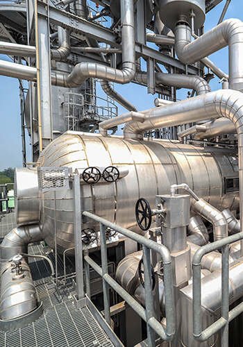
The safe and economical operation of a boiler depends on the precise control of key parameters. Among these, the stability of the boiler drum liquid level is particularly important, as it reflects the dynamic balance between the boiler load and the feedwater flow.
If the drum liquid level is too high, the steam-water separation process is compromised. This can lead to saturated steam carrying water, which causes a sudden drop in steam temperature and an increase in steam salinity. In turn, this may damage critical components like the superheater and steam turbine.
On the other hand, if the boiler drum liquid level is too low, the boiler’s water circulation is disrupted. This can result in overheating of the water walls and, in severe cases, may lead to tube explosions.
Therefore, maintaining the stability of the boiler drum liquid level requires precise and constant adjustment during boiler operation. The accuracy and reliability of the measurement methods and control schemes for the drum liquid level are essential to ensuring safe and stable operation.
Measurement of Boiler Drum Liquid Level
To achieve accurate monitoring of the boiler drum liquid level under all operating conditions, a water level gauge configuration based on multiple measurement principles should be used. This ensures reliability and consistency in measurement across varying boiler conditions.
For instance, in a 230 t/h oil and gas-fired boiler in a company’s project, several types of water level gauges are installed on the boiler drum. These include two mica two-color non-blind-area water level gauges, two electric contact water level gauges, and three differential pressure water level gauges.
The two-color water level gauge and the electric contact water level gauge display the boiler drum liquid level on-site and provide a reference for monitoring. These gauges are crucial for immediate on-site readings and help operators stay informed of the boiler drum’s status.
Meanwhile, the signal from the differential pressure water level gauge serves as another reference. After pressure correction, it accurately reflects the true liquid level of the drum. This corrected value is then used for the automatic adjustment and control of the boiler drum liquid level, ensuring stability in the system.
1.1 Mica Two-Color Non-Blind-Area Water Level Gauge
A mica two-color non-blind-area water level gauge is installed on each of the two drum heads. This setup allows operators to visually check the drum liquid level, providing a straightforward method for on-site monitoring.
The water level TV monitoring system, which is equipped with a camera, transmits the image to the central control room’s large-screen monitor. This enables remote monitoring, allowing operators to keep track of the liquid level from a distance.
The two-color water level gauge operates based on the principle of a communicating vessel and the refraction characteristics of light. Red and green light sources are positioned behind the liquid cavity of the gauge body.
The light is projected into the liquid cavity through a special window. In the steam phase region, the red light is projected forward, while the green light is obliquely refracted on the wall. In the liquid phase region, the green light is projected forward, and the red light is refracted. This creates the distinct “red for steam and green for water” effect.
However, because the two-color water level gauge operates based on the communicating vessel principle, it has certain limitations. The temperature in the communicating vessel is lower than in the drum, resulting in the water column being lower than the actual liquid level in the boiler drum. Additionally, as the pressure in the drum increases, the deviation (Δh) between the measured result and the actual liquid level becomes larger. The empirical values are shown in Table 1.
Table 1. Deviation Between the Measurement Result of the Two-Color Water Level Gauge and the Actual Drum Liquid Level
| Drum Pressure/MPa | 16.14 – 17.65 | 17.66 – 18.39 | 18.40 – 19.60 |
|---|---|---|---|
| Δh/mm | 51 | 102 | 150 |
1.2 Electric Contact Water Level Gauge
An electric contact water level gauge is installed on each of the two boiler drum heads. This setup allows operators to read the boiler drum liquid level value on the secondary meter of the gauge, providing a convenient way to monitor the liquid level on-site.
The working principle of the electric contact water level gauge is based on the significant difference in electrical conductivity between water and steam. The gauge’s measuring cylinder is connected to the drum through water and steam outlet pipes, forming a communicating vessel with the boiler drum.
Ceramic electrodes are distributed along the cylinder, with some electrodes submerged in water and others exposed to steam. This configuration takes advantage of the fact that electrodes in water have lower impedance compared to those in steam, which have higher impedance.
By detecting these changes in impedance, the gauge converts the variations into current fluctuations, which are used to accurately measure the liquid level.
Since the electric contact water level gauge also operates on the communicating vessel principle, the measured value will be lower than the actual liquid level in the boiler drum.
1.3 Differential Pressure Water Level Gauge
Three differential pressure water level gauges are installed on the boiler drum shell. Each gauge consists of a single-chamber balance container and a differential pressure transmitter. The positive pressure side of the transmitter is connected to the chamber’s pressure pipe, and the negative pressure side is connected to the opposite pipe. The principle involves calculating the drum water level by measuring the static pressure, as shown in Figure 1.
Figure 1. Schematic of the Differential Pressure Water Level Gauge
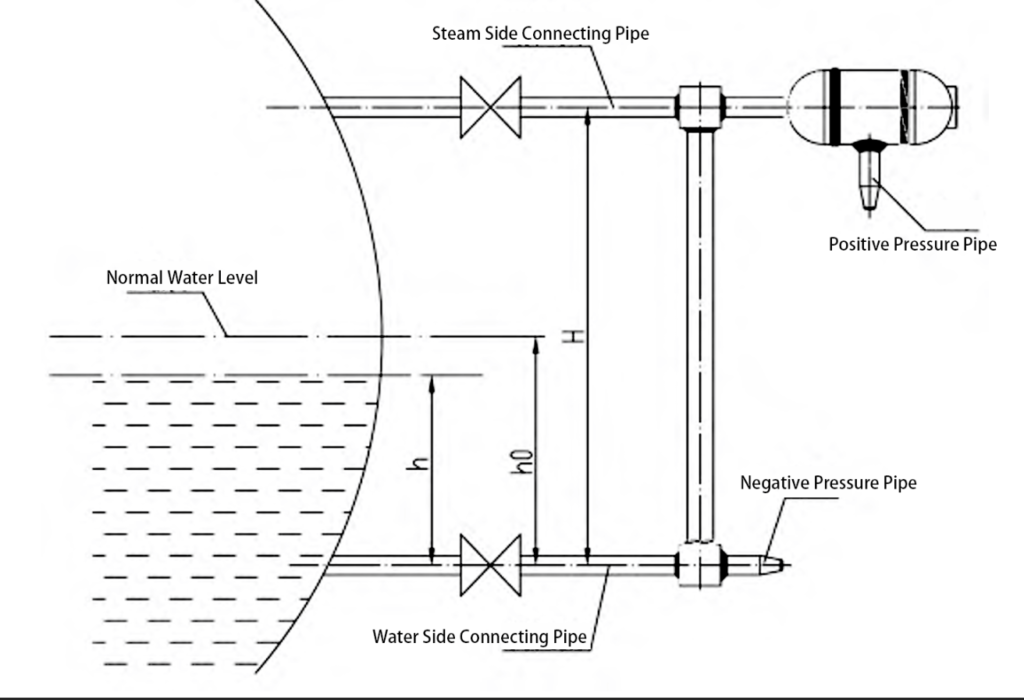
The water in the balancing part is always at a certain level. We use some math to figure out the pressure in different parts. The density of the water and steam changes with the pressure in the boiler drum. We can look up these numbers in a table. Then we use more math to find out the water level.
1.4 Notes on Water Level Measurement
The sampling pipe should pass through the inner wall partition of the boiler drum, and the orifice should avoid unstable steam-water conditions such as near the safety valve exhaust, drum water inlet, or downcomer pipe openings. If unavoidable, a flow stabilizing device should be installed. The pressure compensation formula for newly installed differential pressure gauges should be checked before use, and drum liquid level tests may be necessary.
2. Control of Boiler Drum Liquid Level
Drum liquid level control is crucial for boiler operation. To keep the boiler drum liquid level within the normal range, the boiler feedwater flow must be adjusted in real time. Typically, a combination of single-element control and cascade three-element control is used. These control methods can be automatically switched at appropriate setpoints, ensuring continuous and stable boiler operation.
The boiler drum liquid level exhibits two key characteristics:
- Delay: The liquid level does not change immediately with feedwater flow adjustments but exhibits a time delay.
- False Liquid Level: When the steam load increases suddenly, the boiler pressure may temporarily drop, causing increased water boiling and a rise in the liquid level, resulting in a false liquid level.
During the early stages of boiler startup (when main steam flow is less than 30% BMCR) or when main steam flow drops to 25% of rated capacity, the single-element control system is typically used. This system is more effective under low-load conditions. For normal or high-load operation, the three-element control system is preferred, as it offers more accurate liquid level adjustments.
2.1 Single-Element Control System
In the single-element control system, the boiler drum liquid level signal is used to control the feedwater flow. The system adjusts the feedwater flow based on the PI controller. When the liquid level is below the set value, the feedwater valve opens more to increase the flow. When the liquid level is above the set value, the valve closes to reduce the flow.
This system is effective at low load or during startup, when steam flow and feedwater flow differ significantly, and the impact of false liquid levels is minimal.
2.2 Cascade Three-Element Control System
The cascade three-element control system uses three signals: boiler drum liquid level, main steam flow, and feedwater flow. The main regulator (PI1) and sub-regulator (PI2) are connected in series to control the drum liquid level and feedwater flow, respectively. The main regulator adjusts the liquid level, while the sub-regulator adjusts the feedwater flow to maintain steam-water balance.
This system effectively prevents interference from false liquid levels by using feedforward control. For example, if the boiler drum liquid level rises due to false readings, the sub-regulator adjusts the feedwater flow to stabilize the system.
3. Conclusion
The boiler drum liquid level is a crucial parameter in the safe and economic operation of a boiler. Using multiple measurement principles, such as two-color water level gauges, electric contact gauges, and differential pressure gauges, ensures accurate and reliable monitoring. The combination of single-element and cascade three-element control systems ensures stable liquid level control under different operating conditions, crucial for the boiler’s safety and efficiency.
References
[1] National Energy Administration. 25 Key Requirements for Preventing Power Production Accidents and Compilation Interpretation (2023 Edition) [M]. Beijing: China Electric Power Press, 2023.
[2] Wen Qunying. Thermal Automatic Control System [M]. Beijing: China Electric Power Press, 2006.
