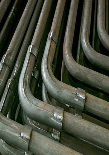
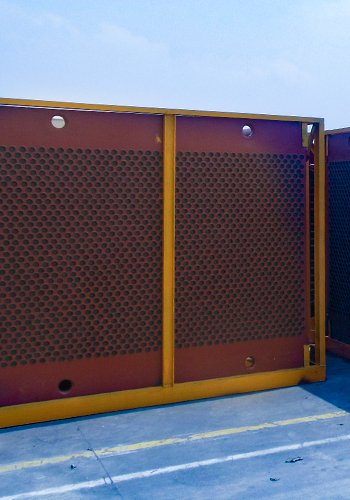
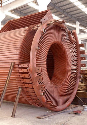
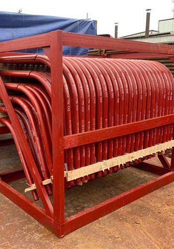
In power plant generators, coal-fired boilers hold a relatively important position. During their production and operation, various heat losses inevitably occur, among which the heat loss from flue gas emission is the largest, accounting for about 65% of the total heat loss. Relevant data shows that when the heating surface of a coal-fired boiler in a power plant is contaminated, the exhaust gas temperature will increase significantly. At present, to effectively reduce heat loss, many power plants have introduced low-temperature economizers. This article analyzes the energy-saving effect of the 330 MW unit low-temperature economizer in a power plant, as follows:
Connection method of the low-temperature economizer
Typically, in a power plant steam turbine, a water intake for the low-temperature economizer is often designed in the low-pressure regenerative extraction section. The temperature of the condensate produced should not be too high and should be below the exhaust gas temperature. After the low-temperature condensate enters the low-temperature economizer, it absorbs the heat from the exhaust gas and finally merges with the main condensate before entering other extraction steam regenerative systems. The economy and stability of the system are affected by the water-side connection method. When the connection method differs, there will be significant differences in the enthalpy increase of the condensate, and the connection method will also affect the operating conditions of the equipment and is closely related to the system economy. When conducting economic analysis, the absorbed heat should be regarded as external waste heat utilization to simplify the problem. Subsequently, from the perspective of boiler efficiency, the low-temperature economizer is emphasized to avoid affecting boiler efficiency, and at the same time, its economy is analyzed using the equivalent enthalpy drop method. The method is relatively simple and highly feasible.
1.1 Equivalent enthalpy drop method
As for the equivalent enthalpy drop method, it primarily calculates the parameters of equipment based on the principle of heat balance. Through this, the enthalpy drop and efficiency of extraction steam can be obtained, demonstrating favorable application advantages in thermodynamic calculations. The main calculation approaches are presented as follows.
(1) For a completely condensing unit, if the specific enthalpy of the steam entering the steam turbine is and the specific enthalpy of the steam exiting the steam turbine is hc , the work done by 1 kg of fresh steam is its actual enthalpy drop, and the enthalpy drop H is calculated as:

(2) For a regenerative extraction steam unit, unlike a completely condensing unit, after the steam enters the steam turbine, it is continuously extracted to heat the condensate. In this case, the enthalpy drop taken away by the extraction steam needs to be considered in the actual calculation of the steam turbine enthalpy drop. So, if the inlet enthalpy is h0 and the outlet enthalpy is hc, the enthalpy drop H is calculated as:

where 1, 2, …, are the values of the extraction steam shares for each section; 1, 2, … h2are the values of the extraction steam specific enthalpy, with the unit kJ/kg; is the number of extraction steam stages; r is the heater extraction steam stage number; Yr is the coefficient of insufficient work done by the steam turbine extraction steam.
Through actual comparison, it can be concluded that compared with a completely condensing unit, the equivalent enthalpy drop of fresh steam in a regenerative extraction steam unit is smaller. Therefore, this article mainly analyzes the equivalent enthalpy drop of a regenerative extraction steam unit.
1.2 New steam enthalpy drop and extraction steam efficiency
Usually, when pure heat enters the No. 1 low-pressure heater, it is used for rotor action and also heats a part of the condensate. The work done by the extraction steam needs to be calculated in detail. According to the heat balance equation, when the extraction steam quantity of the No. 1 low-pressure heater is reduced by 1 kg, its drain will also be reduced by 1 kg, and the formula for calculating the heat reduction value is:

In the formula, γ2 represents the heat reduction value, with the unit of kJ/kg; hdl stands for the value of the extraction steam heat of the No. 1 low – pressure heater, in the unit of kJ/kg; hw3 indicates the value of the drain heat, with the unit of kJ/kg; α2-1 is the value of the share of 1 kg of extraction steam being displaced from the No. 1 low – pressure heater to the No. 2 low – pressure heater; q2 is the value of the heat generated by 1 kg of extraction steam in the No. 2 low – pressure heater, with the unit of kJ/kg. In this part, the amount of extraction steam that returns to do work and condenses is 1-α2-1, and the No. 3 low – pressure heater will receive the corresponding drain. The formula for calculating the extraction steam required to heat this part of the drain is:

where α3-1 is the value of the extraction steam obtained by the No. 3 low-pressure heater from the No. 1 low-pressure heater, with the unit %; τ3 is the value of the specific enthalpy increase of 1 kg of water in the No. 3 low-pressure heater, with the unit kJ/kg; q3 is the value of the heat discharged by 1 kg of extraction steam in the No. 3 low-pressure heater, with the unit kJ/kg; he3 is the value of the extraction steam heat of the No. 3 low-pressure heater, with the unit kJ/kg.
The extraction steam H1 going to the steam turbine to do work is calculated by formula (11):

1.3 Thermodynamic analysis of the regenerative extraction steam system
For the regenerative extraction steam system, there are two heating methods, namely the drain discharge type and the collection type. Under different heating methods, the thermodynamic calculation methods also differ.
(1) Thermodynamic calculation of the drain discharge type: The calculation formula is:

where τj is the value of the specific enthalpy increase of 1 kg of water in the j jth low-pressure heater, with the unit kJ/kg; h-y is the value of the water specific enthalpy at the exit of the jth low-pressure heater, with the unit kJ/kg; j is the value of the heat generated by 1 kg of steam in the jth low-pressure heater, with the unit kJ/kg; hj is the value of the heat of the jth low-pressure heater, with the unit kJ/kg; is the value of the drain specific enthalpy, with the unit kJ/kg; γj is the value of the heat generated by 1 kg of drain in the jth low-pressure heater, with the unit kJ/kg.
(2) Thermodynamic calculation of the collection type: The thermodynamic calculation method is as follows. The formula for γj is the same as formula (12).

Dynamic analysis of the low-low temperature economizer
Usually, when the load of a power plant unit changes, it will directly affect the amount of condensate and also cause changes in data such as the outlet water temperature of the low-temperature economizer. Compared with the rated operating condition, calculating relevant data in a dynamic operating condition is more complex. When actually calculating relevant parameters, a trial-and-error method can usually be chosen to obtain the final result.
2.1 Model analysis
When the amount of condensate Dd≥25t/h , the heat transfer coefficient K is a fixed value. If the inlet flue gas and condensate water temperatures do not change, when the condensate water flow increases, the flue gas temperature and condensate water temperature will decrease, and there will be a larger heat transfer amount and average heat transfer temperature difference. The calculation equation is:

where D0 is the value of the fresh steam flow, with the unit kg/s; Qd is the value of the heat transfer amount, with the unit kJ; cy is the value of the flue gas constant pressure specific heat capacity, with the unit kJ/(kg·°C); Vy is the value of the flue gas volume, with the unit m3/h; ty is the value of the inlet flue gas temperature, with the unit °C; y is the value of the outlet flue gas temperature, with the unit °C; cd is the value of the condensate water constant pressure specific heat capacity, with the unit kJ/(kg·°C); Dd is the value of the condensate water flow, with the unit t/h; t”d is the value of the outlet condensate water temperature, with the unit °C; t’d is the value of the inlet condensate water temperature, with the unit °C; A is the value of the convective heat transfer area, with the unit m2; △t is the value of the average heat transfer temperature difference, with the unit °C.
Under the condition of continuously changing condensate water amount, the adjustment of the extraction steam amount needs to be done well. The formula for calculating the outlet water temperature t’j is:

where Vj is the value of the condensate water volume, with the unit m3/h; t”j is the value of the outlet water temperature, with the unit °C; t’j is the value of the inlet water temperature, with the unit °C; Dj is the value of the extraction steam flow, with the unit kg/s; q is the value of the unit extraction steam heat release, with the unit kJ/kg; Dm is the value of the initial operating condition extraction steam flow, with the unit kg/s; △p0 is the value of the extraction steam pipe pressure difference, with the unit MPa; is the value of the extraction steam pipe pressure, with the unit MPa; Pi is the value of the extraction steam pressure, with the unit MPa; Ps is the value of the saturation pressure, with the unit MPa; ts is the value of the saturation temperature under the heater pressure, with the unit °C; δ1 is the value of the saturation temperature, with the unit °C; τ is the value of the heat absorbed by the internal condensate water, with the unit kJ/kg; Q is the value of the unit heat transfer amount, with the unit kJ/kg.
2.2 Dynamic calculation method
For a changing operating condition, in the actual calculation process, when the amount of condensate does not change, the above formulas can be used to calculate data such as the outlet water temperature and the equivalent enthalpy drop increment. In short, using the calculation model proposed above, the influence of a certain variable on the economy can be calculated.
3 Energy-saving analysis of the 330 MW unit low-temperature economizer in Xx power plant
3.1 Unit parameters
The Xx power plant uses a 330 MW subcritical coal-fired water-cooled unit, selects a B&WB-1025/18.44-M type boiler, and sets an intermediate once-through reheater, a cold-state solid slagging pulverized coal furnace. A two-regulation wind DRB type pulverized coal rotating fuel injector is used; the pulverizing system selects a primary air drying and carrying pulverized coal, positive pressure direct blowing method. The main design parameters of the boiler are shown in Table 1.
Table 1 Main design parameters of the boiler
| Project | Rated operating condition | Maximum continuous output |
|---|---|---|
| Rated evaporation capacity/(t·h) | 936.50 | 906.00 |
| Reheat steam quantity/(t·h→) | 846.30 | 19.53 |
| Superheated steam outlet pressure (gauge pressure)/MPa | 18.34 | 18.44 |
| Reheat steam outlet pressure (gauge pressure)/MPa | 4.14 | 3.88 |
| Drum pressure (gauge pressure)/MPa | 19.43 | 19.53 |
| Superheated steam temperature/°C | 543 | 543 |
| Reheat steam temperature/°C | 542 | 542 |
| Boiler efficiency/% | 93.16 | 93.14 |

where V0 is the value of the theoretical air volume, with the unit m3/h; β is the fuel characteristic coefficient.
3.2 Project introduction
Through an investigation of the Xx power plant site, it was found that its unit has a problem of excessive exhaust gas temperature, with an annual average exhaust gas temperature reaching 125 °C, and the maximum temperature reaching 145 °C. The emission of a large amount of high-temperature waste heat has seriously affected the economy of the unit, specifically manifested as follows: 1) Low boiler efficiency. Usually, for every 15 – 20 °C increase in exhaust gas temperature, the boiler efficiency will decrease by 1%. Thus, it can be seen that there is a large space for improving the efficiency of the boiler in this power plant. 2) Under the condition of continuously increasing exhaust gas temperature, the working environment of equipment such as fans will be seriously affected, and the operation of the unit will be threatened. 3) Under the condition of continuously increasing exhaust gas temperature, there will be a large amount of flue gas, reducing the working efficiency of the dust collector. 4) Under high exhaust gas temperature, the water consumption will increase, resulting in a large amount of heat loss, and excessive spraying will increase the power consumption of the pump. 5) A large amount of water vapor will appear, aggravating the corrosion of the chimney.
3.3 Analysis of coal type characteristics
In the operation of the 330 MW unit in the Xx power plant, the calorific value of the coal entering the furnace is required to be ≥ 23 027.4 kJ (5 500 kcal). To achieve the goal of energy conservation and consumption reduction, the power plant selects two coal types for blending to ensure that the calorific value requirement of the coal is met. Some data of the design coal type are shown in Table 2.
Table 2 Some data of the design coal type Unit:%
| Project | Received base carbon mass fraction | Received base hydrogen mass fraction | Received base oxygen mass fraction | Received base nitrogen mass fraction | Received base sulfur mass fraction |
|---|---|---|---|---|---|
| Design coal type | 52.20 | 2.47 | 8.42 | 0.98 | 0.73 |
| Check coal type 1 | 50.84 | 2.68 | 10.84 | 0.61 | 0.82 |
| Check coal type 2 | 50.61 | 2.37 | 9.82 | 0.86 | 0.99 |
The annual average temperature is 125 °C, and the maximum temperature is 145 °C. To ensure that the low-temperature economizer system can reduce the flue gas temperature to the target value, the inlet flue gas temperature is set to 145 °C to ensure that the flue gas temperature meets the actual requirements.
3.4 Energy-saving analysis of the low-temperature economizer
Thermodynamic system energy-saving analysis. Firstly, conduct flue gas energy-saving calculations. The theoretical calculation formula for flue gas enthalpy h0y is:

where VR02 is the value of the volume of triatomic molecules, with the unit m3/h ; hRO2, hN2, hH2O are respectively the values of the specific enthalpy of triatomic molecules, nitrogen, and water vapor at a certain temperature, with the unit kJ/kg; V0N2, V0H2O are respectively the values of the volumes of and water vapor, with the unit m3/h.
The theoretical value h0k and actual value hk of air enthalpy are calculated as follows:

where V0 is the value of the theoretical air volume, with the unit m3/h; β is the fuel characteristic coefficient.
According to formula (28), calculate the fly ash enthalpy hfh:

The actual flue gas enthalpy hy is calculated as:

where ω(Aαγ) is the mass fraction of received base ash; αfh is the mass fraction of fly ash in the total ash; hh is the value of the specific enthalpy of ash at a certain temperature, with the unit kJ/kg; α is the coefficient of excess air.
Because the volume of SO₂ is smaller than that of CO₂, the enthalpy value of CO₂ is used to replace that of SO₂. Through the above formula, the flue gas components and related parameters are obtained. At the same time, according to the heat balance calculation, the design parameters of the low-temperature economizer are obtained.
2) Calculation of steam-water parameters in the extraction steam regenerative system. Through the equivalent enthalpy drop calculation, the extraction steam parameters are obtained. Through the comparative analysis of the parameters of the extraction steam regenerative system before and after the installation of the low-temperature economizer, it is concluded that it will not have a significant impact on the overall system parameters. When the low-temperature economizer is connected in parallel at both ends with the No. 3 low-pressure heater and the inlet water temperature is higher than 80 °C: the extraction steam quantity on the low-temperature side will decrease, while the extraction steam quantity on the high-temperature side will increase, resulting in a large cold source loss and also affecting the steam turbine efficiency.
Through the equivalent enthalpy drop method for thermo-economic analysis, the increment of the extraction steam equivalent enthalpy drop is obtained as 24.53 kJ/kg, the system economy is relatively improved (by 1.87 °C), the coal consumption for power generation is reduced by 1.87 g/(kW·h), the heat consumption reduction is 44.85 kJ/kg, and the annual coal savings is 3003.7 t. Thus, it can be concluded that when the low-temperature economizer takes water from the inlets of No. 1 and No. 2 and is connected across No. 3, it can achieve the safe operation of the unit, effectively reduce the exhaust gas temperature, and reduce the coal consumption for power generation by 1.87 g/(kW·h). This connection method can further improve the system economy. Calculated at 5000 h/a, it can save 3003.7 t/a of standard coal, equivalent to a fund of 9.048 × 10⁵ yuan.
Conclusion
In summary, during the operation of power plant units, in order to obtain better economic benefits and reduce operation losses, effective measures need to be taken to do a good job in the energy-saving transformation of the units. The low-temperature economizer has obvious energy-saving advantages, and applying it to power plant boilers and steam turbine equipment can obtain good energy-saving effects. Taking the 330 MW unit of Xx power plant as an example, the low-temperature economizer is applied to it, relevant parameters are designed, and the economy of applying the low-temperature economizer is analyzed. The research concludes that the application of the low-temperature economizer can effectively reduce the coal consumption for power supply and improve the energy-saving level of the system. At the same time, the system is simple to control, has low operating requirements, and only damaged parts need to be replaced during actual maintenance. In short, applying the low-temperature economizer to the 330 MW unit of a power plant can improve the operation efficiency of the unit and is worthy of promotion.
Author: Wang Sen
References:
[1] Zhang Hairu, Wu Hao. Numerical analysis of the optimization of the inlet cavity structure, expansion joints and pipeline wear of the low-temperature economizer of a 330 MW unit [J]. Environmental Engineering, 2023, 41 (Suppl 2): 824 – 827.
[2] Wen Baohui. Design and application of the low-temperature economizer of a 330 MW coal-fired unit [J]. Shanxi Chemical Industry, 2022, 42(2): 230 – 231.
[3] Liu Haifeng. Research on energy-saving technologies of a 660 MW ultra-supercritical unit in a power plant [J]. China High-Tech, 2022(20): 21 – 23.
[4] Xie Qingliang, Xie Shanxiang, Wang Zhengyang. Comprehensive comparison between the conventional low-temperature economizer and the heat pipe low-temperature economizer in a coal-fired power plant [J]. China Environmental Protection Industry, 2022(11): 15 – 18.
[5] Zhou Huijuan. Research on the transformation of adding a low-speed function to the circulating water of a 660 MW unit in a thermal power plant [J]. Water Supply and Drainage, 2023, 59(Suppl 1): 234 – 237.
