The superheater pipeline of a boiler in a company’s captive power plant had a tube burst. To understand the cause, several tests were carried out on the burst tube and adjacent sections. These included macroscopic inspection, chemical composition analysis, hardness testing, and metallographic examination.
The results revealed that the tube burst was caused by long-term high-temperature operation. Before the burst, the tube overheated. At high temperatures, the steel’s strength dropped sharply, leading to plastic deformation. This caused the diameter to increase and the wall thickness to decrease, eventually resulting in fracture and bursting. The adjacent pipe section had a microstructure of massive ferrite and carbide particles, with few bainite region traces. The carbides aggregated and grew, mostly in granular form at grain boundaries and within grains. The material’s spheroidization grade was 4, indicating it was at the end of its service life.
1. Research Background
The superheater pipeline of a boiler in a company’s captive power plant burst. The pipeline had been in operation for 6 years, with a material of 12Cr1MoVG and a specification of (outer diameter × wall thickness). Operating conditions: The inside of the tube contained high-pressure, high-temperature steam, with an internal temperature of approximately and a pressure of 13.7 MPa. The external environmental temperature of the pipeline was around . The location of the internal pipeline of the superheater is shown in Figure 1. The tube that burst was numbered 11#, and the burst opening was located on the straight section of the back smoke side of the 11# tube. The numbers of the surrounding tubes were 9#, 10#, and 12#. The material condition of the burst tube 11# and the adjacent pipe sections 9#, 10#, and 12# was evaluated, and a failure cause analysis was carried out from aspects such as macroscopic inspection of the burst opening, composition, hardness, and metallography.
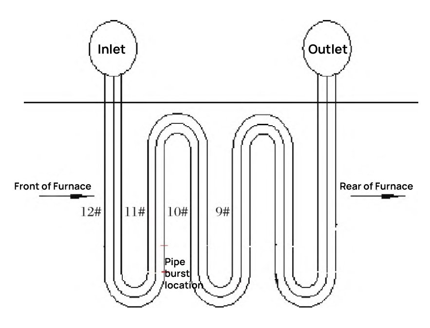
Figure 1 Schematic Diagram of Tube Burst Location
The dimensions of the burst tube and the surrounding straight pipe sections were measured, and the results are shown in Table 1. Referring to the nominal dimension of , the outer diameter and wall thickness were measured at a location approximately 100 mm from the burst opening on the 11# tube. The 11# tube exhibited a significant increase in outer diameter and a significant decrease in inner wall thickness, with a bulging rate of 7.5% and a thinning rate of 18.2%, showing abnormal bulging characteristics due to short-term rapid overheating. No significant bulging characteristics were found in the surrounding pipelines of the failed tube [1].
2. Analysis and Testing
2.1 Macroscopic Inspection
The macroscopic photos of the burst tube are shown in Figure 2 and Figure 3. The burst opening was large, and the crack extended from the inner wall to the outer wall. The burst opening was in the shape of a thin-lipped horn and was accompanied by significant plastic deformation. No other secondary cracks were found in the surrounding area. After the burst, the 11# pipeline was bent and deformed as a whole.
As shown, referring to the nominal dimension of ϕ42 mm × 6 mm, the outer diameter and wall thickness were measured at a location approximately 100 mm from the burst opening on the 11# pipe. The 11# pipe exhibited a significant increase in outer diameter and a significant decrease in inner wall thickness, with a bulging rate of 7.5% and a thinning rate of 18.2%, showing abnormal bulging characteristics due to short-term rapid overheating. No significant bulging characteristics were found in the surrounding pipelines of the failed pipe.

Fig. 2 Macro picture of 11# burst pipe and sampling location
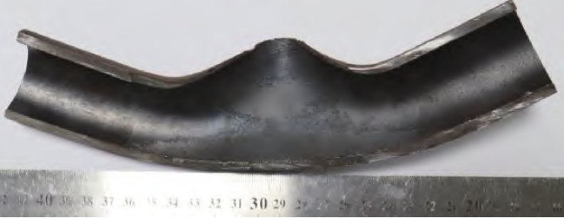
Fig. 3 Photograph of the inner wall of 11# burst pipe
Table 1 Dimensional Measurement Results
| Tube Sample | Measurement Location | Mean Value 1 | Mean Value 2 | Mean Value 3 | Average Value |
|---|---|---|---|---|---|
| 9# | Outer Diameter | 42.53 | 42.54 | 42.52 | 42.50 |
| Wall Thickness | 5.99 | 5.94 | 6.02 | 6.00 | |
| 10# | Outer Diameter | 42.80 | 42.80 | 42.50 | 43.10 |
| Wall Thickness | 5.97 | 5.90 | 6.00 | 6.00 | |
| 11# | Outer Diameter | 45.15 | 44.98 | 45.30 | 45.28 |
| Wall Thickness | 4.91 | 4.66 | 4.72 | 5.36 | |
| 12# | Outer Diameter | 42.57 | 42.56 | 42.58 | 42.56 |
| Wall Thickness | 5.99 | 5.98 | 6.00 | 6.00 |
2.2 Chemical Composition Testing
Spectroscopic composition analysis was performed on the sampled tubes. The composition was referred to GB/T 5310 – 2017 “Seamless Steel Tubes for High-Pressure Boilers”, as shown in Table 2. The results showed that the chemical compositions of the 9#, 10#, 11#, and 12# cut pipe sections met the composition requirements of 12Cr1MoVG in GB/T 5310 – 2017.
Table 2 Chemical Composition of Specimens (%)
| Item | C | Mn | Si | P | S | Cr | Mo | V |
|---|---|---|---|---|---|---|---|---|
| 9# | 0.137 | 0.54 | 0.24 | 0.013 | 0.001 | 1.07 | 0.31 | 0.21 |
| 10# | 0.135 | 0.54 | 0.24 | 0.013 | 0.001 | 1.12 | 0.31 | 0.21 |
| 11# | 0.129 | 0.54 | 0.24 | 0.013 | 0.002 | 1.12 | 0.31 | 0.21 |
| 12# | 0.099 | 0.52 | 0.24 | 0.012 | 0.002 | 1.11 | 0.29 | 0.20 |
| GB/T 5310 – 2017 | 0.08 – 0.15 | 0.40 – 0.70 | 0.17 – 0.37 | ≤0.025 | ≤0.010 | 0.90 – 1.20 | 0.25 – 0.35 | 0.15 – 0.30 |
2.3 Hardness Testing
Hardness measurement was carried out on the metallographic surface according to GB/T 4340.1 – 2009 “Metallic Vickers Hardness Test – Part 1: Test Method”, with a load P=1kg and a load holding time of 10s. The test results are shown in Table 3. The Vickers hardness results showed that the hardness of the base material near the burst tube was 134HV, with a significant decrease in hardness, slightly lower than the lower limit value (lower limit value of 135HV) specified in GB/T 5310 – 2017.
Table 3 Micro Vickers Hardness Results (HV1)
| Item | Sampling Location | Hardness |
|---|---|---|
| 9# | Straight Section at Thickness | 186, 188, 186 |
| 10# | Straight Section at Thickness | 194, 193, 182 |
| 11# | Approximately 100 mm from Burst Opening at Thickness Section | 134, 135, 134 |
| 12# | Straight Section at Thickness | 185, 181, 188 |
2.4 Metallographic Inspection
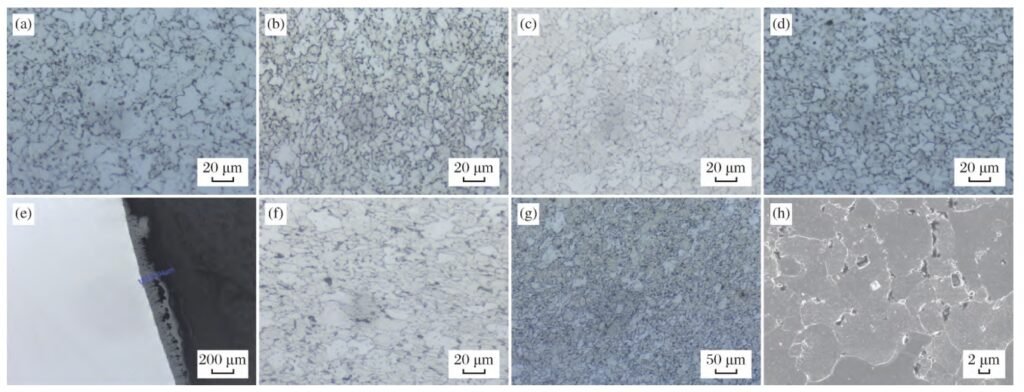
(a) The metallographic structure of 9# pipe; (b) The metallographic structure of 10# pipe; (c) The metallographic structure of 11# pipe; (d) The metallographic structure of 12# pipe; (e) The measurement of the oxide layer depth of 11# pipe; (f) The metallographic structure at the fracture source of the burst opening of 11# pipe; (g) The metallographic structure at the fracture source of the burst opening; (h) The fracture source of the burst opening (SEM).
Fig. 4 Microstructure morphology of different areas
(1) Microstructures of 9#, 10#, and 12#
The microstructures of 9#, 10#, and 12# were all massive ferrite + carbide particles, with only a few traces of bainite regions. The carbides significantly aggregated and grew, and most of them were distributed in granular form at the grain boundaries and within the grains. The spheroidization grade of the microstructure was 4, and the grain size was 7 – 8 grades. There was a transition layer with certain thickness of oxidation corrosion and crack characteristics between the inner and outer wall oxide scales and the substrate, as shown in Figure 4 (a), 4 (b), and 4 (d). After long-term operation, the material microstructure suffered severe creep damage and aging [3].
(2) Microstructure at 11# Burst Opening
At the 11# burst opening, the microstructure was massive ferrite + carbide particles + equiaxed ferrite + pearlite. The carbides precipitated in chains at the grain boundaries, and there were many carbide particles dispersed within the grains. There was no original bainite region characteristic, and the spheroidization grade of the microstructure was 5, and the grain size was 8 – 9 grades [4], as shown in Figure 4(c). The depth of the oxide layer of the 11# tube was approximately 200μm, as shown in Figure 4 (e).
(3) Microstructure at the Fracture Origin of 11# Burst Opening
At the fracture origin of the 11# burst opening, the microstructure was massive ferrite + carbide particles + equiaxed ferrite + pearlite. The grains were elongated, with obvious traces of plastic deformation. There were many fine equiaxed ferrite and dot-like pearlite in the surrounding area of the massive ferrite, as shown in Figure 4(f),4(g). It can be seen from Figure 4 (h) that there were a large number of intergranular pores and microcracks near the crack [5], and the arrangement direction was perpendicular to the maximum working stress direction.
The test results of the cracks and microstructure characteristics near the burst tube showed that the main burst opening crack extended along the grains from the outer surface to the inner wall. The secondary cracks on the outer surface had typical characteristics of creep-initiated cracks. A large number of intergranular pores and microcracks were arranged perpendicular to the maximum working stress direction [6]. The microstructure characteristics of the burst tube: completely ferrite + carbide particles, with a large number of directional intergranular cracks and pores arranged from the outer wall to the inner wall near the burst tube, and the original bainite traces completely disappeared.
3 Result Analysis
3.1 Macroscopic and Physical Characteristics
The macroscopic inspection and related tests on the 12Cr1MoVG boiler superheater burst tube and adjacent tubes showed several key features. The burst opening was large, with the crack spreading from the inner wall to the outer wall. It had a thin-lipped horn shape and was accompanied by substantial plastic deformation. There were no other secondary cracks or corrosion marks around. After the burst, the 11# pipeline was bent and deformed as a whole. The burst tube had an abnormal bulging, with a significant increase in outer diameter and a decrease in wall thickness due to short-term rapid overheating. In contrast, the adjacent pipelines did not show such bulging characteristics.
3.2 Chemical Composition and Hardness
The chemical compositions of 9#, 10#, 11#, and 12# all met the requirements of 12Cr1MoVG in GB/T 5310 – 2017, with no abnormalities. However, the hardness value of the burst tube was slightly lower than the lower limit specified in GB/T 5310 – 2017 for 12Cr1MoVG. When compared to the surrounding pipelines, the hardness of the burst tube decreased significantly.
3.3 Metallographic Microstructure
The metallographic microstructure detection provided important insights. Firstly, according to the “DL/T 773 – 2016 Spheroidization Rating Standard for 12Cr1MoV Steel in Thermal Power Plants”, the material was rated for spheroidization. All of 9#, 10#, 11#, and 12# had a spheroidization grade of 4, while the 11# burst tube had a grade of 5. There was an increase in the oxide scale thickness on the inner wall side of the burst opening of the 11# tube. Secondly, compared to the adjacent pipelines, the metallographic structure of the burst tube changed significantly. It consisted of massive ferrite + carbide particles + equiaxed ferrite + pearlite. The equiaxed ferrite + pearlite was the product of eutectoid decomposition of supercooled austenite, indicating that the burst tube had overheated before the burst. Based on the material handbook, the Ac1 temperature of 12Cr1MoVG was around 780℃, and the Ac3 temperature was around 890℃. Thus, the temperature of the 11# pipeline before the burst was between 780℃ and 890℃, far exceeding the maximum service temperature of the material.
4. Conclusion
All the inspected pipelines had been operating at high temperatures for a long time, and their strengths gradually decreased with time. Compared with the pipelines adjacent to the burst tube, the metallographic structure of the burst tube showed equiaxed ferrite + pearlite, with eutectoid decomposition of supercooled austenite, indicating that the location of the burst tube experienced local overheating before the burst. Local overheating was the direct cause of this tube burst.
Author(s): Wang Shiru, Lai Jiandong, Chen Yihui, Corn Daiping
References:
[1] Chen Xuancai, Yang You. Cause Analysis of Boiler Water Wall Overheating Damage [J]. Petrochemical Equipment Technology, 2007, 28(2):38.
[2] Standardization Technical Committee of Power Station Metal Materials in the Power Industry. DJ/T 939 – 2016 Technical Guideline for Supervision of Boiler Heating Surface Tubes in Thermal Power Plants [S]. Beijing: China Electric Power Press, 2016.
[3] Tang Renjian, Lu Wei, Jun Yinlin, et al. Carbide Microstructure in 12Cr1MoV Steel after Long-Term High-Temperature Aging [J]. Journal of Tongji University (Natural Science Edition), 2006, 34(1):106.
[4] Tang Pengjie, Cai Zhaolei, Han Xu. Cause Analysis of Cracking of 20 Steel Superheater Tubes in a Waste Heat Boiler [J]. Physical Testing, 2022, 40(5):41.
[5] Yang Xiaojie, Yuan Xingdong, Ma Hongtao. Cause Analysis of Cracking of Heating Pipelines [J]. Physical and Chemical Testing (Physical Volume), 2011, 47(5):327.
[6] Zhao Dawei, Zhao Guoxian, Li Pingquan, et al. Cause Analysis of Cracking in P110 Oil Casing during Hydrostatic Testing [J]. Physical and Chemical Testing (Physical Volume), 2010, 46(1):56.
[7] Ren Yan. Leakage Analysis and Treatment of High-Pressure Auxiliary Steam Heating Pipeline in a Waste Heat Boiler [J]. Electric Power Safety Technology, 2021, 23(1):63.
[8] Li Guiying, Li Shanshan, Li Jiankai. Cause Analysis of Bursting of Steel Tubes for High-Pressure Boilers in a Dry Quenching Coke Plant [J]. Shandong Metallurgy, 2023, 45(2):31.
[9] Li Mengsheng, Wang Lifang, Xie Xia, et al. Predicting the Remaining Life of Boiler High-Temperature Pipelines by the Hardness Method [J]. Journal of Hefei University of Technology (Natural Science Edition), 2004(5):518.
